1.
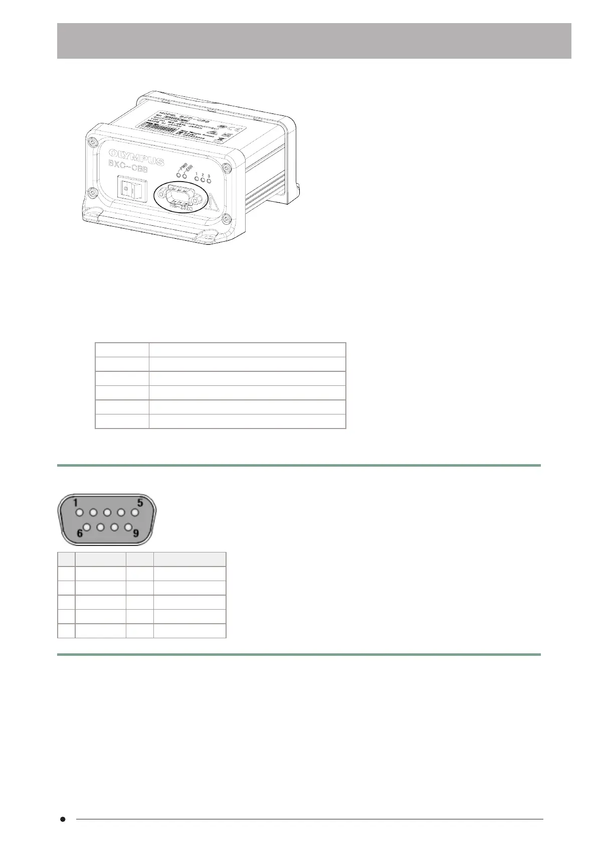
Connect RS-232C cable to the connector on the front panel of the control box BXC-CBB. (See the figure below.)
l
To connect to a PC, use a D-Sub9 pin (female)-D-Sub9 pin (female) straight-through cable. (If you use an
incorrect cable, the product may be damaged.)
l
The connector on the front panel of the control box BXC-CBB: D-sub9pin DCE assignment
l
Mating clamping screw: #4-40 UNC
l
The following table shows the settings for communication (Fixed value)
Baudrate 19200 [bps]
Data bit 8 [bits]
Parity even
Stop bit 1 or 2 [bits] (switching the setting not required) *
Terminator CR+LF
Flow control None
*The setting of the stop bits for communicating from the Host-PC to BXC-CBB. The setting of the stop bits for
communicating from BXC-CBB to the Host-PC is fixed to “2”.
TIP:
If connecting to a device other than a PC, do so at your own risk. Refer to the following table for the connections.
No. Signal name I/O Function
2 RXD OUT Transmitted data
3 TXD IN Received data
5 GND — Signal ground
7 RTS IN Request to send
8 CTS OUT Clear to send
Pins not indicated are not internally connected and pins 7 and 8 are internally connected to each other.
24
3.12 Connecting cables3. Setup procedures