2.3 Rear and side panels
25
CLV-190 INSTRUCTION MANUAL
Ch.2
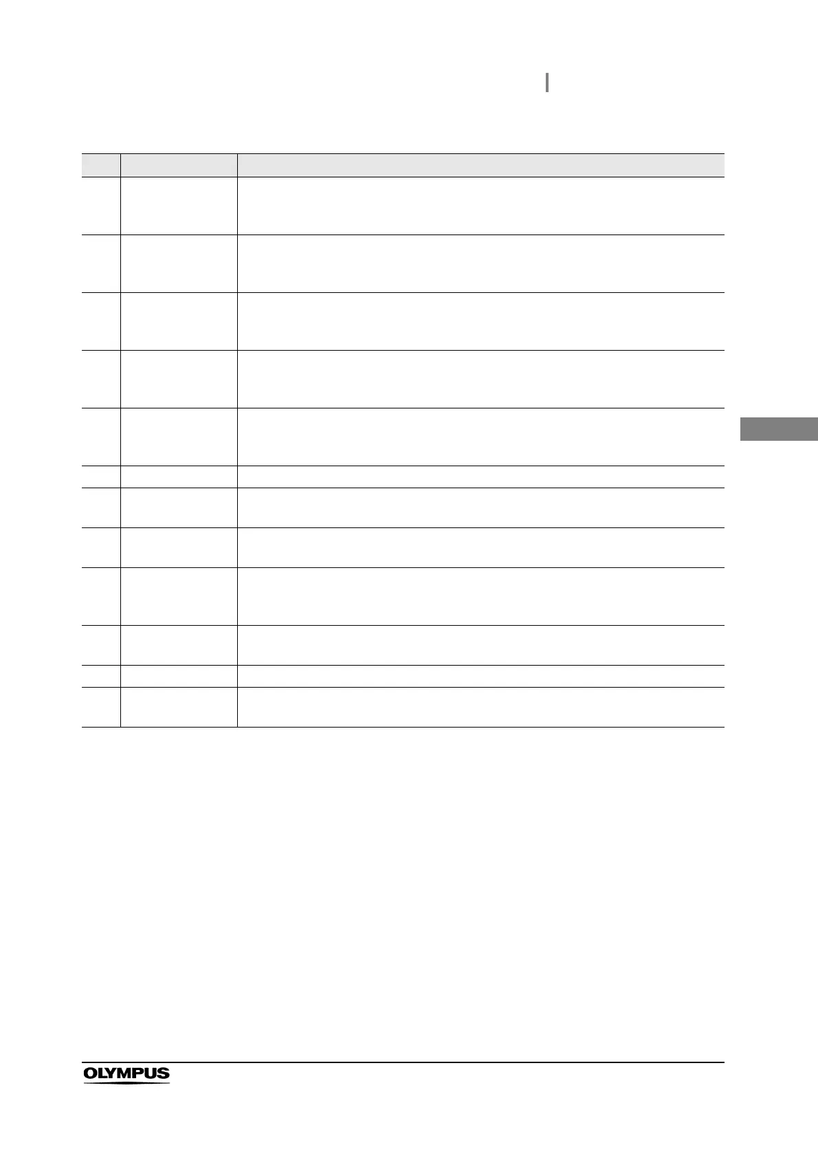
No. Nomenclature Description
1 CV2 terminal This terminal is the receptacle for the digital light source cable (MAJ-1933) for use with
the video system center.
→ Section 3.6, “Connection of the video system center”
2 CV1 terminal This terminal is the receptacle for the light source cable (MAJ-1941) for use with the
video system center.
→ Section 3.6, “Connection of the video system center”
3 LINK-OUT terminal This terminal is the receptacle for the communication cable (MAJ-1942, MAJ-1948) for
use with the endoscope position detecting unit or endoscopic surgical system. See the
instruction manual for the video system center connected to the light source.
4 Lamp ignition mode
switch
Press this switch to select between automatic or manual ignition of the examination
lamp.
→ Section 3.5, “Selection of the lamp ignition mode”
5 Potential
equalization
terminal
This terminal is connected to a potential equalization terminal of the other equipment
connected to the light source. The electrical potential of the equipment are equalized.
6 Ventilation grills The air in the light source is exhausted from the grills for cooling.
7 Foot switch
terminal
This terminal is the receptacle for the foot switch (MAJ-1391).
→ Section 3.7, “Connection of the foot switch”
8 AC power inlet Connect the provided power cord to supply the AC power via this inlet.
→ Section 3.8, “Connection to the AC mains power supply”
9 UPD terminal The terminal is the receptacle for the CLV-UPD cable (MAJ-1898) for use with the
endoscope position detecting unit. See the instruction manual for the video system
center connected to the light source.
10 Lamp cover This cover has to be removed to replace the examination lamp.
→ Section 6.2, “Removal of the lamp”
11 Lamp chamber The lamp is inserted to this chamber.
12 Water container
holder
This holder is used for the installation of the water container.
→ Section 3.4, “Installation of the water container”