Nomenclature & Functions
12
i--SPEED LT, i--SPEED 2
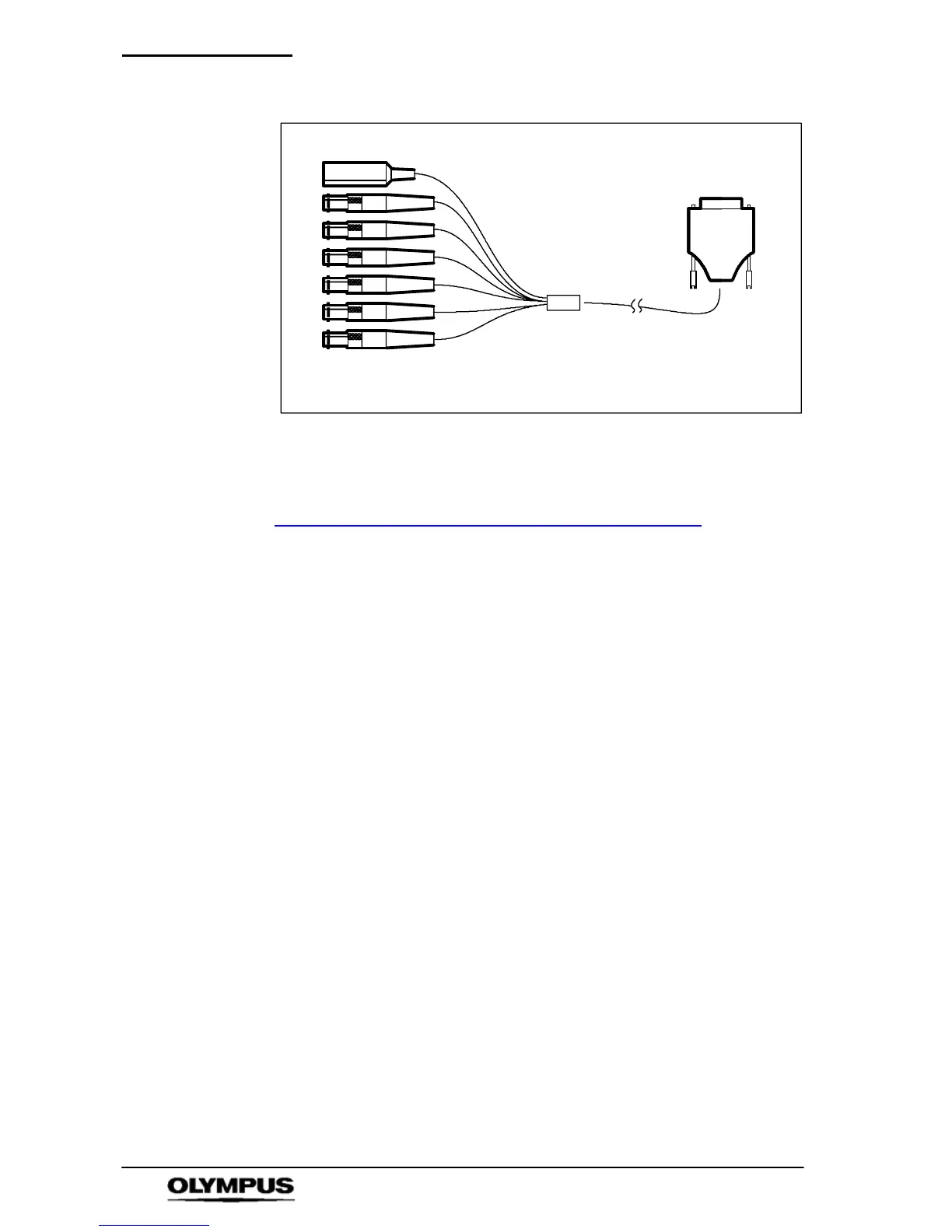
Feature connec tor ca ble
Trigger Input / Trigger Switch: This connector (and the
supplied trigger switch if required) are used to trigger the camera
while recording is in progress. Further details are provided in
Chapter 8 “Understanding the Olympus
i--SPEED 2”.
When the trigger is set to 0%, the trigger counter is set to the
length of the memory, so that the trigger point appears at the
beginning (0%) of the final video clip. A setting of 100% will
cause the recording to stop immediately, placing the trigger
event at the end of the v ideo clip.
The signal is TTL level and the user may select rising edge or
falling edge trigger options.
The trigger input contains a “pull--up” resistor to enable the
supplied trigger switch to be used without further electronics. It
should be noted that the trigger switch provides a falling edge.
In practice, the trigger switch also produces a rising edge
because of switch bounce, but this cannot be guaranteed.