System Connecti on
23
i--SPEED LT, i--SPEED 2
Chapter 4 System Connection
As described in Chapter 1,thei-SPEED 2 camera system can be
configured in two ways using a Controller Display Unit (CDU) or
Ethernet via connection to a PC or Laptop. The i-SPEED LT
camera system may only be configured using a Controller Display
Unit (CDU)
.
Refer to the connection diagrams shown below and connect the
system as appropriate.
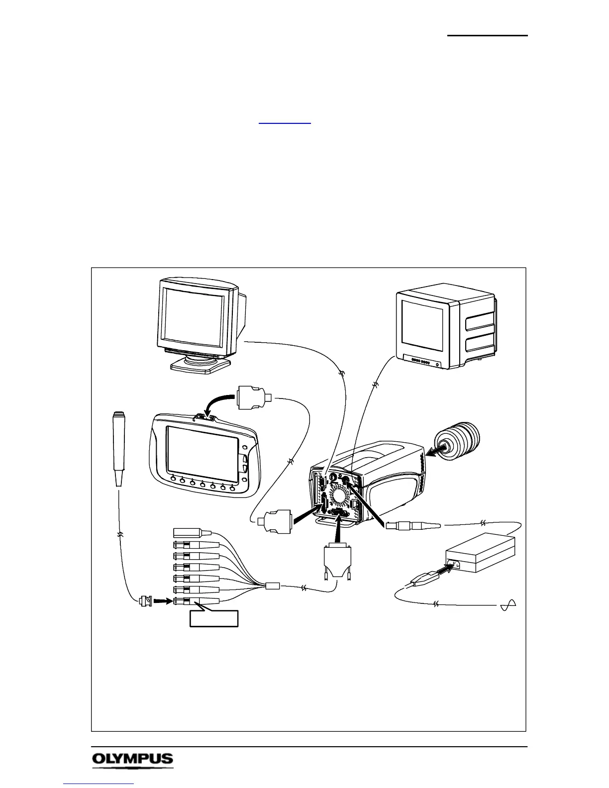
4.1 Controller Display Unit (CDU)
Key
1 T rigger switch 6 Power supply unit (PSU)
2 CDU (Controller Display Unit) 7 Mains power cable
3 Contr oller cable 8 C--Mount lens
4 Camera 9 VGA cable
5 Feature connector cable 10 Composite video BNC cable
1
2
3
4
5
6
7
8
3
TRIG IN
*not all items shown are supplied in the standard set, see Chapter 2.
9
10
Optional
PC/TV monitor