Nomenclature & Functions
13
i--SPEED LT, i--SPEED 2
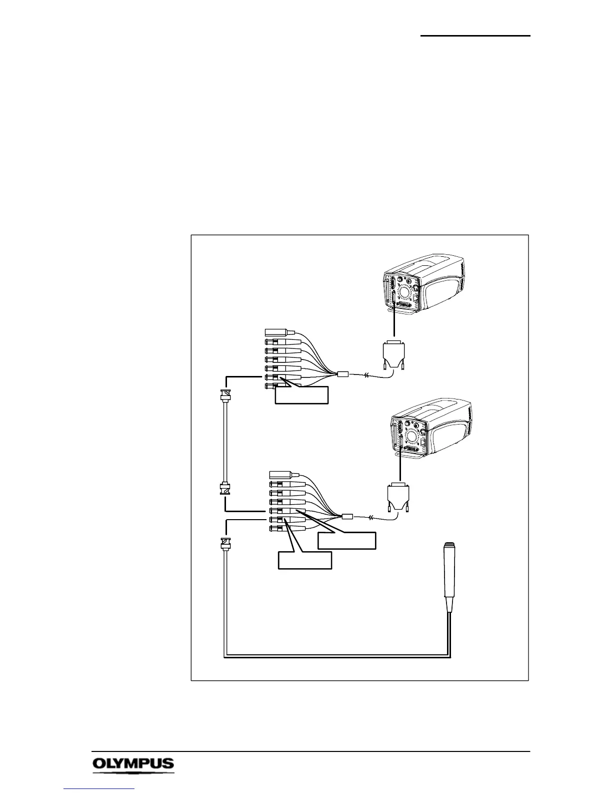
Trigger Output: This output is TTL compatible and gives a 1
microsecond wide active high pulse. The rising edge signifies
the start of the first integration period of the sensor to occur after
recording has stopped. This connector may be used to cause
another camera to trigger after the end of this camera’s
recording. In this way a series of cameras may work in a
daisychain.
When daisy chain operation is used, the first cameras trigger
point may be selected by the user, but it is recommended that
the second camera’s trigger position is set to 0%.
Camera 1
TRIG IN
TRIG OUT
Camera 2
Trigger
switch
BNC (not supplied)
TRIG IN
In addition to all
other connections