HGT1 User Manual
30 OMICRON
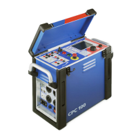
Figure 8-6: HGT1 settings according to EN 50522
Figure 8-6 shows the settings to be considered when measuring step and touch voltage with the HGT1:
The 100 Hz range (10 – 114 Hz) is recommended, since frequencies higher than 100 Hz are not
important for the measurement.
In the above example, 1 kΩ is selected as input impedance according to the EN 50522 recommendation
for touch voltage measurements.
► If required, select an alternative setting, for example High Z, in order to measure the prospective
touch voltage.
Note: The High Z setting is needed for measurements according to IEEE 81.
► Check if the two settings for the detection frequency equal the frequency of the injected current.
► Refer to the chapter 5.1 "Frequency range selection" on page 17 for information on how to adapt the
frequency.
Now the step and touch voltage at distinct locations can be measured according to Figure 8-5: on
page 29. The automatic detection of step and touch voltages requires the following workflow in order to
avoid a faulty measurement:
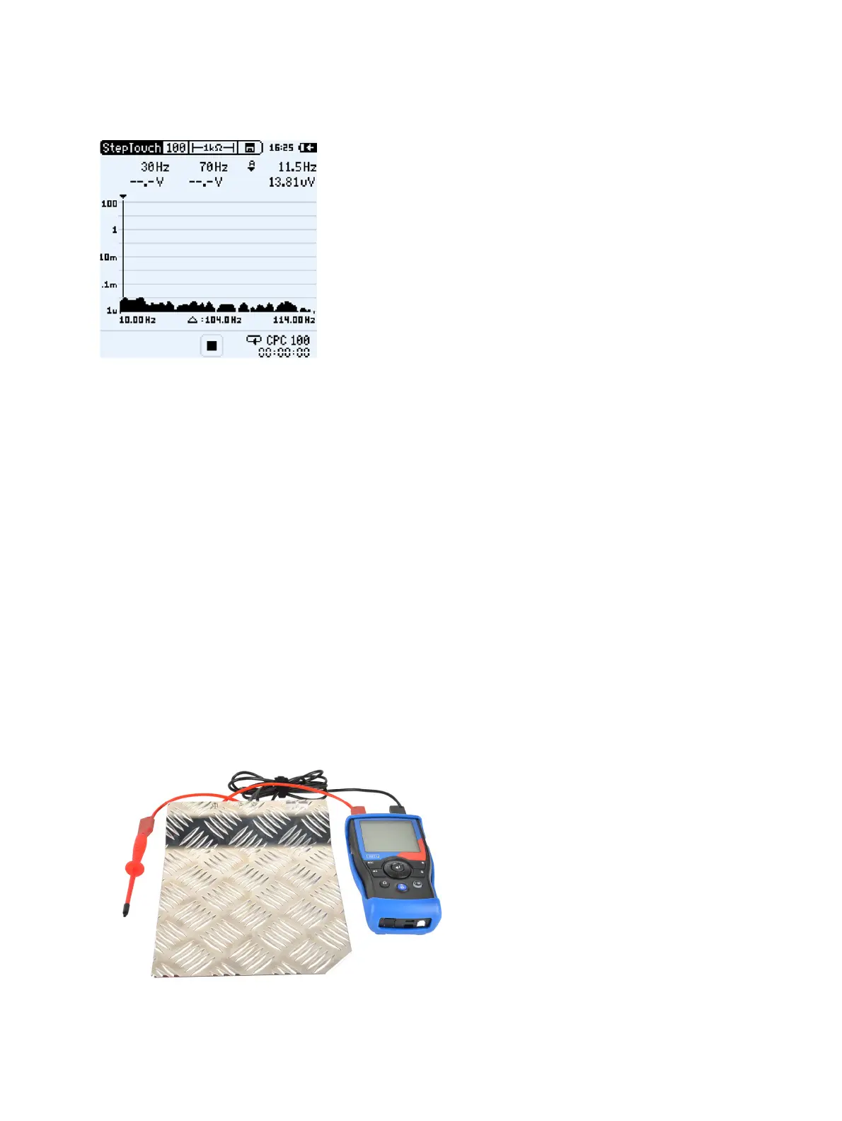
5. Depending on the standard you follow, connect the metal plate (EN 50522) or the ground rod
(IEEE 81) to the HGT1, using the black banana cable.
6. Connect the probe to the HGT1, using the red banana cable.
Figure 8-7: HGT1 hardware setup according to EN 50522
HGT1
Metal plate (ground electrode)
Probe

 Loading...