HGT1 User Manual
26 OMICRON
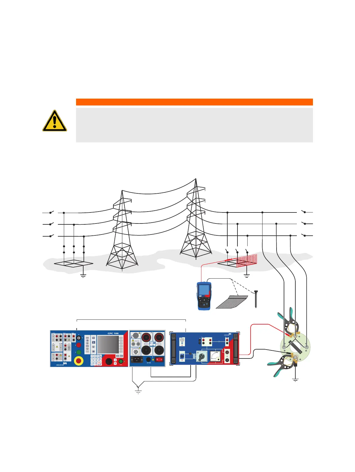
8 Step and touch voltage measurements
8.1 Measurements without PTM (stand-alone)
1. Follow the instructions in chapter 3 "Connecting the CP CU1 to a power line" of the CP CU1 User
Manual in order to connect the CP CU1 to the power line under test.
2. If criterion 3 is met, establish the measurement setup as shown in Figure 8-1 below.
Figure 8-1: Step and touch voltage measurement setup
WARNING
Death or severe injury caused by high voltage or current possible
► Use a grounding set to ground the power line at the near end whenever you handle
the measurement setup inside the danger zone (for example when changing
connections at the CP GB1 between measurement loops).
I AC
I AC
BOOSTER
V
200
400
600
20 A 50 A
10 A
100
A
CPC 100
GROUND CPC 100 CP GB1
CP GB1
30V : 600V
2.5A : 100A
BOOSTER
I AC V1 AC V SENSE
I OUT
C
P
C
U1
CPC 100 CP CU1
CP GB1
I OUT
HGT1
a
esc
Ω
EN 50522:2011 IEEE 81-2012
HGT1

 Loading...


