OMICRON 27
Step and touch voltage measurements
Note: In order to measure valid step and touch voltage values, the distance between the grounding
system under test and the remote substation must be taken into account. IEEE 81 recommends a
minimum distance of five times the maximum dimensions of the grounding system to avoid overlapping
of the ground potential rise of both the grounding system and the current probe. EN 50522 recommends
a minimum distance of 5 km, no matter the size of the grounding system. In general, the setup must
represent worst case conditions, which could occur during a single line fault. This must be clarified for
each individual grounding system.
3. When checking the fourth criterion, use the dedicated template on the CPC 100 by following this path
in the file operations view:
Templates > Grounding Systems > Step&Touch using HGT1
4. Choose the template matching the current range selected on the CP CU1.
The template contains the following test cards:
• Connection (comment test card, showing the necessary connections)
• Output (sequencer test card, used for the injection of the test current)
• Version (version check for Excel template)
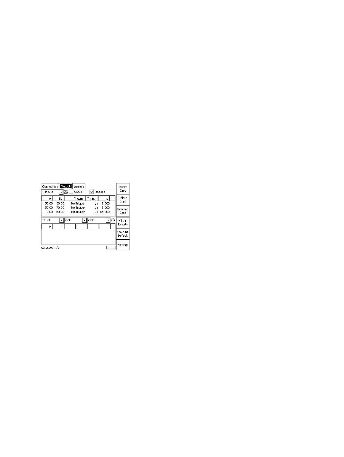
Figure 8-2: Output test card of the Step&Touch using HGT1 template on the CPC 100
Figure 8-2 above shows settings in the Output test card of the Step&Touch using HGT1 template. The
sequence consists of 3 states, which are applied in an endless loop, since Repeat is activated in the test
card:
• Injection of the test current at 30 Hz for 2 s (measuring touch voltage at a distinct location at 30 Hz)
• Injection of the test current at 70 Hz for 2 s (measuring touch voltage at a distinct location at 70 Hz)
• No injection for 56 s (to be able to move to the next measurement location in the substation)
In order to save time, the injection of the test current can also be remote-controlled by adapting the
sequencer test card accordingly as shown in Figure 8-4 below. In the second column, additional
measurement of voltage at the DC input is activated.
► Optional: Connect a walkie-talkie, which is used as a receiver, to the CPC 100’s VDC input, by using
an adapter as shown in Figure 8-3 below.

 Loading...