HGT1 User Manual
28 OMICRON
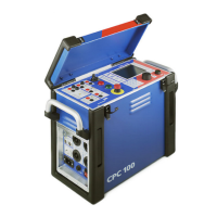
Note: This is no accessory available from OMICRON!
Figure 8-3: Adapter for the connection of a walkie-talkie to the CPC 100
► Plug the headphone jack into the walkie-talkie’s headphone socket and connect the banana plugs to
the CPC 100’s VDC input.
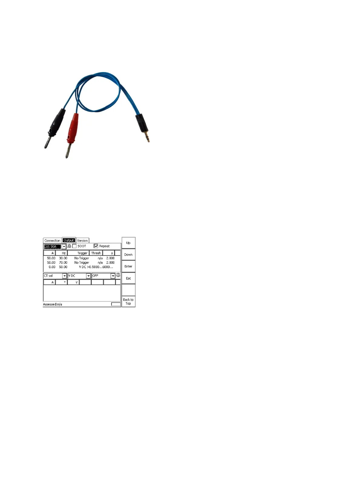
In the example shown in Figure 8-4 below, the voltage at the headphone socket was about 1 V when
pressing the talk button on the walkie-talkie that was used as a sender. Hence, a threshold level of 0.5
V is reasonable. By pressing the talk button on the sender walkie-talkie, the measurement sequence
starts from the first state again and the voltage at a distinct location can be measured instantly, without
waiting for state 3 of the Output test card to complete.
Figure 8-4: Output test card of the Step&Touch using HGT1 template on the CPC 100, adapted for
remote-controlled current injection
EN 50522 and IEEE 81 consider different ways of testing step and touch voltage. Table 8-1 below
illustrates the differences.

 Loading...