OMICRON 33
Step and touch voltage measurements
8.2 Measurements with PTM (using a Windows tablet)
1. Follow the instructions in chapter 3 "Connecting the CP CU1 to a power line" of the CP CU1 User
Manual in order to connect the CP CU1 to the power line under test.
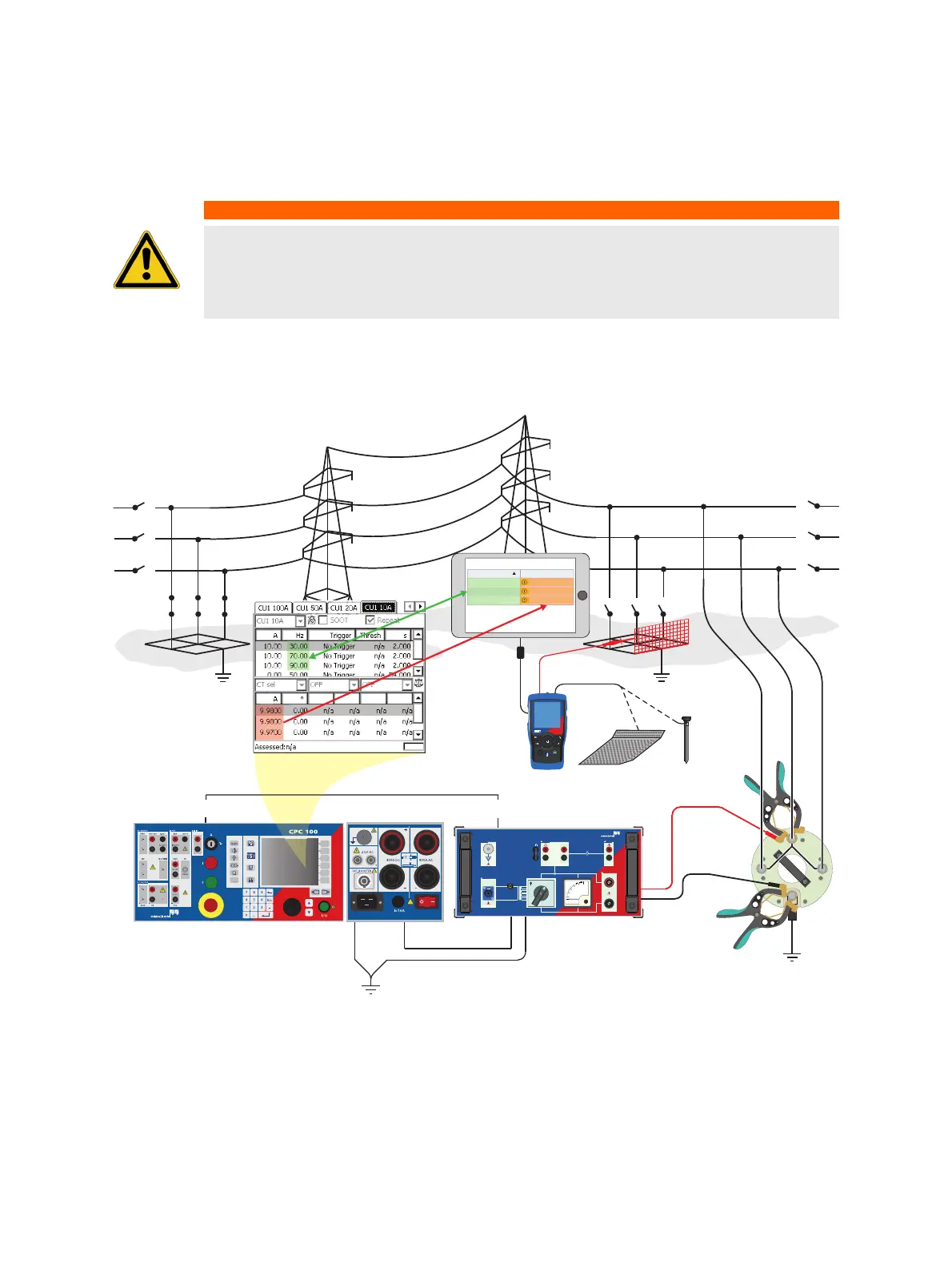
2. If criterion 3 is met, establish the measurement setup as shown in Figure 8-9 below.
Figure 8-9: Step and touch voltage measurement setup when using PTM on a tablet
Note: In order to measure valid step and touch voltage values, the distance between the grounding
system under test and the remote substation must be taken into account. IEEE 81 recommends a
minimum distance of five times the maximum dimensions of the grounding system to avoid overlapping
of the ground potential rise of both the grounding system and the current probe. EN 50522 recommends
WARNING
Death or severe injury caused by high voltage or current possible
► Use a grounding set to ground the power line at the near end whenever you handle
the measurement setup inside the danger zone (for example when changing
connections at the CP GB1 between measurement loops).
I AC
I AC
BOOSTER
V
200
400
600
20 A 50 A
10 A
100
A
CPC 100
GROUND CPC 100 CP GB1
CP GB1
30V : 600V
2.5A : 100A
BOOSTER
I AC V1 AC V SENSE
I OUT
C
P
C
U1
CP CU1
CP GB1
I OUT
Frequency Current
30.00 Hz
70.00 Hz
90.00 Hz
A
A
A
z
7
z
Hz
HGT1
a
esc
Ω
EN 50522:2011 IEEE 81-2012
HGT1

 Loading...