HGT1 User Manual
34 OMICRON
a minimum distance of 5 km, no matter the size of the grounding system. In general, the setup must
represent worst case conditions, which could occur during a single line fault. This must be clarified for
each individual grounding system.
3. When checking the fourth criterion, use the dedicated template on the CPC 100 by following this path
in the file operations view:
Templates > Grounding Systems > PTM
4. Open the file corresponding to your power frequency and navigate to the test card matching the
current range selected on the CP CU1.
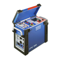
Figure 8-10: CU1 10 test card of the PTM template on the CPC 100
Figure 8-10 above shows settings in the CU1 10 test card of the PTM template. The sequence consists
of 4 states, which are applied in an endless loop, since Repeat is activated in the test card:
• Injection of the test current at 30 Hz for 2 s (measuring touch voltage at a distinct location at 30 Hz)
• Injection of the test current at 70 Hz for 2 s (measuring touch voltage at a distinct location at 70 Hz)
• Injection of the test current at 90 Hz for 2 s (measuring touch voltage at a distinct location at 90 Hz)
• No injection for 54 s (to be able to move to the next measurement location in the substation)
5. Start the injection by pressing the I/0 button on the CPC 100.
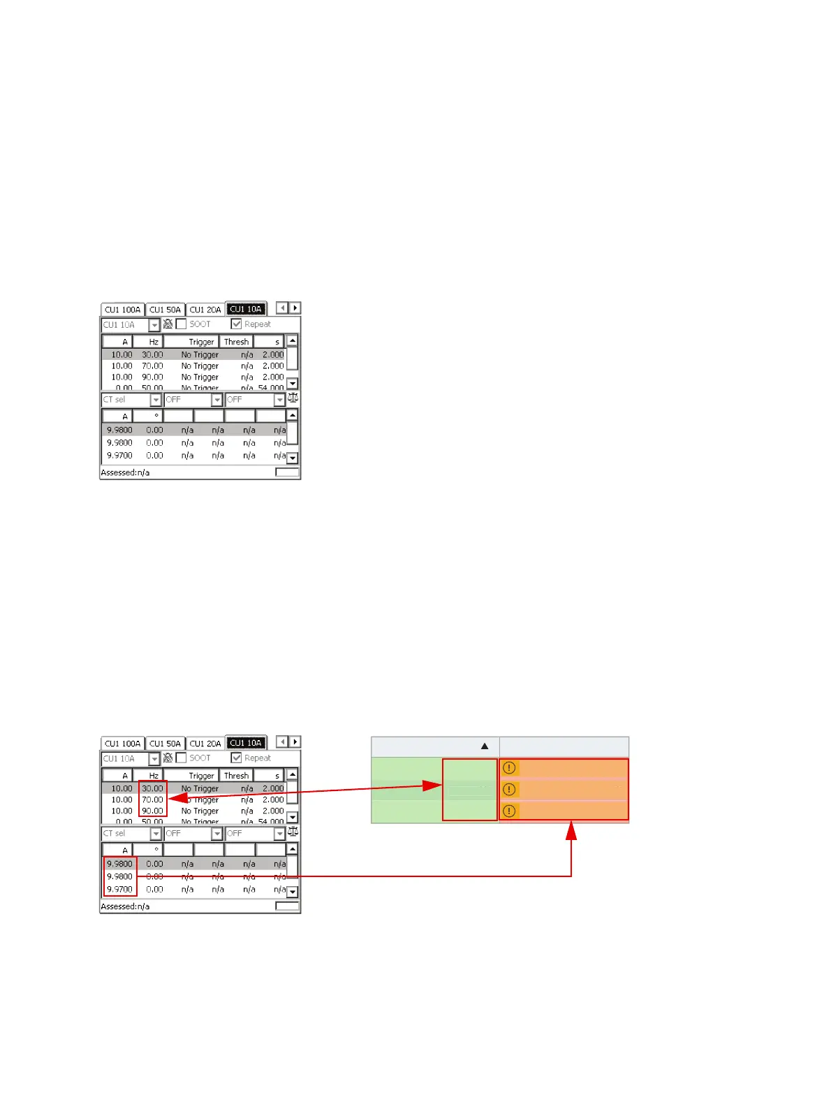
6. Start PTM on the tablet and enter the CPC 100’s current readings for each defined frequency under
Settings and Conditions. Also verify that the frequency selections in the sequencer test card and
under Settings and conditions match.
Figure 8-11: Enter the current readings under the Settings and Conditions section in PTM
EN 50522 and IEEE 81 consider different ways of testing step and touch voltage. Table 8-2 below
illustrates the differences.
Frequency Current
30.00 Hz
70.00 Hz
90.00 Hz
A
A
A
7
9

 Loading...