HGT1 User Manual
36 OMICRON
7. Set the HGT1’s USB mode to COM port to enable communication with the tablet running PTM.
(Refer to 5.1 "System Settings" on page 16 for more information on how to change the USB mode).
8. Connect the HGT1 to the tablet using the HGT1’s USB connector and the delivered USB cable.
As soon as the HGT1 is recognized by PTM, it is locked and cannot be operated via its buttons any
longer.
Now the step and touch voltage at distinct locations can be measured according to Figure 8-12: on
page 35. The automatic detection of step and touch voltages requires the following workflow in order to
avoid a faulty measurement:
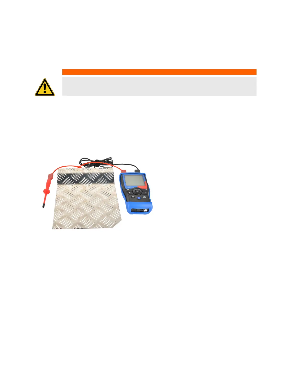
9. Depending on the standard you follow, connect the metal plate (EN 50522) or the ground rod
(IEEE 81) to the HGT1, using the black banana cable.
10.Connect the probe to the HGT1, using the red banana cable.
Figure 8-13: HGT1 hardware setup according to EN 50522
11.Start the current injection loop by pressing the I/O button on the front panel of the CPC 100.
12.a) If you measure according to EN 50522, place the metal plate on the ground and step on it.
b) If you measure according to IEEE 81, drive the ground rod approximately 150 mm into the ground,
one meter away from the object under test.
13.Connect the probe to the object under test.
Note: It is important to establish a good contact to the object. This could sometimes be cumbersome
if the object is painted with an insulating layer. One option is to remove the layer with a file. The
HGT1’s filter adapts to the connected impedance. The adaption results in a temporary increase of
the voltage over the entire frequency spectrum. Hence, by starting the measurement BEFORE the
probe is connected to the object, faulty values could be measured, since the values during adaption
of the filter could be higher than the values actually caused by the injected current.
14.Start the measurement in PTM section Measurement.
15.After the measurement is finished, move to the next location and and take measurements whenever
test current is injected.
WARNING
Death or severe injury caused by high voltage or current possible
► Never connect the HGT1 to the tablet without using the provided USB isolator.
HGT1
Metal plate (ground electrode)
Probe

 Loading...