MPD 800 User Manual
16 OMICRON
Indicators
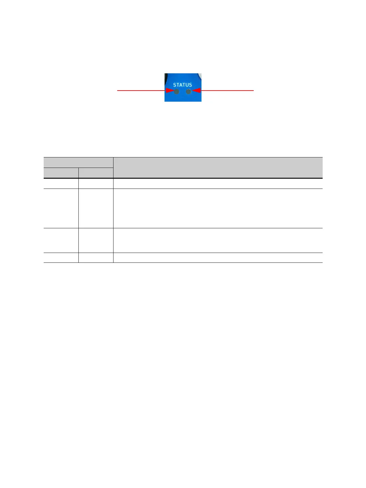
Figure 2-4: MPD 800 acquisition unit indicators (LEDs)
Each MPD 800 acquisition unit is equipped with 2 LEDs (blue and red) for displaying the unit’s status or
malfunctions. The following tables depict the condition and description of the two LEDs.
Integration into systems
The MPD 800 acquisition unit, CPL1, CPL2 and the V-to-AC-adapter are designed as a system. It is
recommended to use them as described in the respective “Designated use” (see 2.2) and “Application”
(see 2.3) chapters. If one or more of the MPD 800 system components need to be integrated into a
existing system, the following additional precautions must be fulfilled:
► If connected to an existing coupling capacitor, locate the MPD 800 acquisition unit in close proximity
of the bottom end connection of the coupling capacitor with a distance of less than one meter.
► If a ground-referenced measurement device which is not part of the MPD 800 system is used
together with the MPD 800 system, use CPL2 due to special grounding restrictions. The maximum
ground-referenced voltage at the input of the low arm capacitor must not exceed 140 V
RMS
under any
measurement condition. Therefore, perform additional precautions to achieve the desired safety
requirements.
Note: If the MPD 800 acquisition unit, CPL1 or CPL2 is accessible during measurement, additional
touch protection is required.
► Do not use the MPD 800 acquisition unit in an electrical path where a failure of the MPD 800
acquisition unit (for example, short or open circuits of measurement inputs) causes:
• a voltage regulation feedback loop to become dysfunctional.
• an over-current protection to become dysfunctional.
• an indicator for hazardous live electrical quantities (IEC 61010-1, VDE 0105-100) to become
dysfunctional.
Table 2-1: Blue and red LED inidications
Condition
Description
Blue LED Red LED
Blinking
Off Device is powered and in standby mode.
Off
Blinking
Error
Device is not working properly.
Check the RBP1 connection or replace the RBP1 connection cable. If the
red LED is still blinking, contact the OMICRON technical support
(see "Support" on page 66).
Off On Device is okay.
Computer does not recognize the device.
Check the fiber-optic connection or replace the fiber-optic cable.
On Off Device is in operation mode (powered and the software is running).