OMICRON 23
MPD 800 measurement system
2.2.3 MCU2 multi-device control unit
Designated use
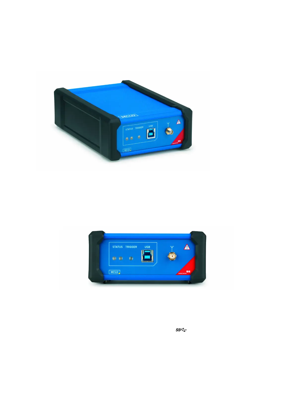
Figure 2-9: MCU2 multi-device control unit
The multi-device control unit (MCU2) is designated to connect one or more OMICRON acquisition units
(for example, MPD 800 or MPD 600) to the PC. It converts optical signals generated by an OMICRON
acquisition unit and transmitted by a fiber-optic cable provided by OMICRON into a standard electrical
communication signal, USB 3.0.
Front panel connections
Figure 2-10: MCU2 front panel
The front panel of MCU2 consists of the STATUS (status LEDs), the TRIGGER (trigger sensor) and the
USB socket.
The USB socket is used to connect MCU2 to the PC. A USB 3.0 or higher port is required to gain the full
functionality of MCU2. USB 3.0 ports are usually marked with the symbol and typically have a blue
insert. The built-in light-sensitive sensor of MCU2 can be used as the TRIGGER source. This sensor is
a photodiode which allows to synchronize to line frequency from artificial light sources.
For description of the STATUS indicators see section "Indicators" on page 25.