OMICRON 25
MPD 800 measurement system
Indicators
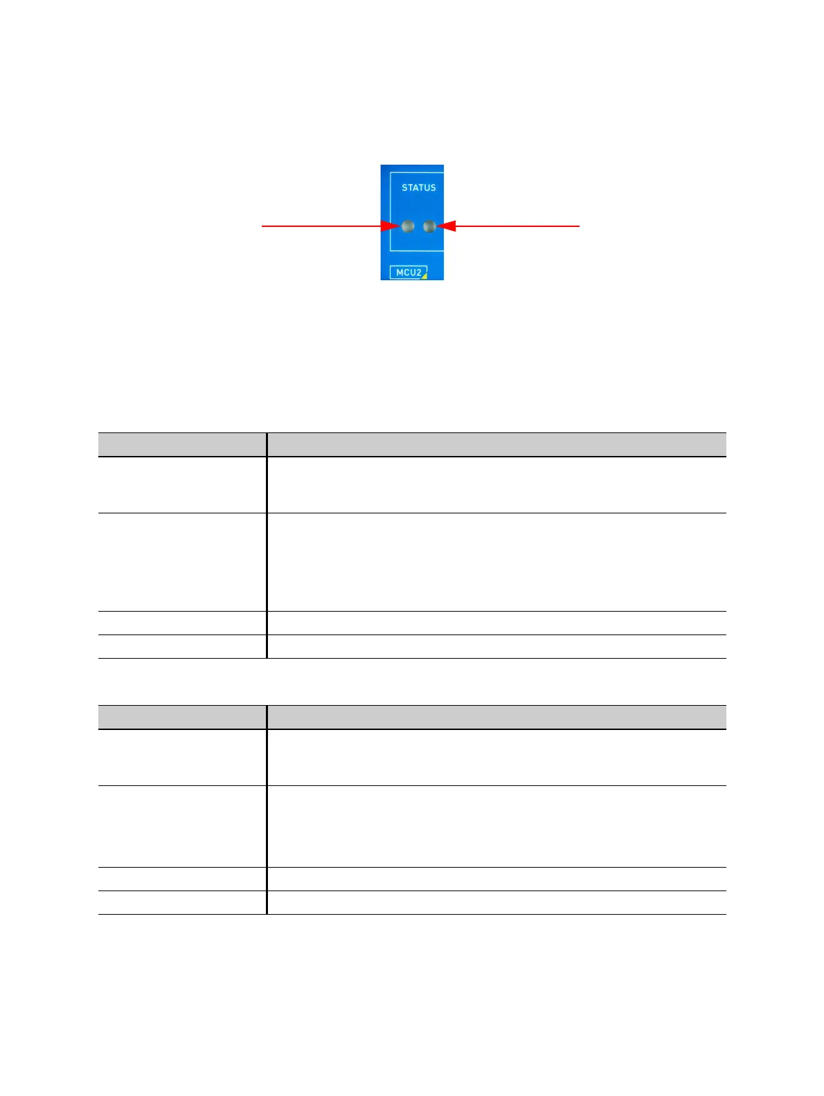
Figure 2-12: MCU2 indicators (LEDs)
MCU2 is equipped with two STATUS indicators (blue and red LEDs) that display the status or
malfunction of the multi-device control unit.
The following tables depict the condition and description of the two LEDs.
Table 2-2: Blue LED indications (on the left-hand side)
Condition Description
Flashing
(A short switch-on phase
and long switch-off phase)
Device is powered and in standby mode.
Blinking
(The switch-on and
switch-off phases are of
the same length)
Device is powered and in active mode. A secondary malfunction or error
was detected and performance might be affected negatively. Check the
fiber-optic connection.
Note: In case of malfunction, contact the OMICRON technical support
(see "Support" on page 66).
Continuous on Device is powered and in active mode.
Continuous off Device is not powered.
Table 2-3: Red LED indications (on the right-hand side)
Condition Description
Flashing
(A short switch-on phase
and long switch-off phase)
Enumeration of the device was unsuccessful.
Blinking
(The switch-on and
switch-off phases are of
the same length)
A malfunction or error has been detected. Device is not working properly
and might be performing a cool-down.
Note: In case of malfunction, contact the OMICRON technical support
(see "Support" on page 66).
Continuous on Device performs a self-check during power-up.
Continuous off No malfunction or error has been detected.