OMICRON 19
MPD 800 measurement system
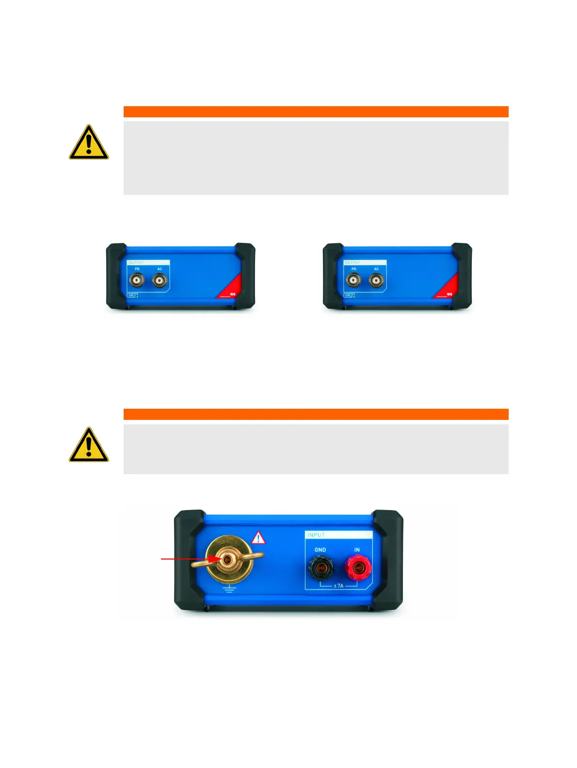
Front panel connections
Figure 2-6: CPL1 and CPL2 front panel
The BNC outputs PD and AC are connected by short, screened cables (< 20 cm) to the BNC inputs at
the MPD 800 acquisition unit accordingly (see "Rear panel connections" on page 14).
Rear panel connections CPL1
Figure 2-7: CPL1 rear panel
The GND or GND wing nut is connected to the ground with a short connection.
► Do not ground the MPD 800 acquisition unit or its accessories in this case.
The IN input is connected to the bottom end connection of the coupling capacitor or test object.
WARNING
Death or severe injury caused by high voltage or current possible
When the test object is energized flashovers or electrical breakthroughs may occur due
to failure of test object. The MPD 800 acquisition unit and CPL1 or CPL2 are not
designed to withstand power frequency fault currents.
► Always observe the minimum safety distance and use personal safety equipment.
WARNING
Death or severe injury caused by high voltage or current possible
An open AC output may carry hazardous voltage.
► Terminate the AC output using a short-circuit cap.