MPD 800 User Manual
14 OMICRON
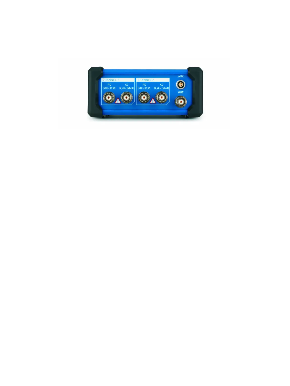
Rear panel connections
Figure 2-3: MPD 800 acquisition unit rear panel
The rear panel of the MPD 800 acquisition unit consists of two input channels, CHANNEL 1 and
CHANNEL 2. Each of the channels consists of two BNC connectors (PD and AC). The PD and AC
connectors correspond to the BNC outputs which can be found on the CPL1 and CPL2 external
quadripoles. The AC output on the external quadripole must be connected to the AC input on the
MPD 800 acquisition unit. Likewise, the PD output on the external quadripole must be connected to the
PD input on the MPD 800 acquisition unit. If no external quadripole is used, the coupling capacitor must
be directly connected to the PD input and the AC input must be left open and the internal quadripole of
the MPD 800 acquisition unit must be activated.
The input impedance of both measurement input types (PD and AC) are complex and therefore
frequency dependent. It is important to note that the AC input is a current measurement input with low
impedance of 4.5 Ω. You must transform a voltage to a current by using the V-to-AC-adapter 100 kΩ,
see 2.2.5 "V-to-AC-adapter" on page 32. The input impedance of the PD input at low frequencies
strongly depends on whether the internal quadripole is activated or not. If the internal quadripole is not
activated, the input impedance is 50 Ω over the rated frequency range. If the internal quadripole is
activated, the input impedance is as low as < 10 Ω at frequencies below 1 kHz, in order to be able to
measure the reactive current of coupling capacitors directly.
An additional BNC connector (OUT) is located on the rear panel. This output carries pulses that is tied
to the unit's test generator or a trigger pulse that is tied to the trigger unit.
Also located on the rear panel of the MPD 800 acquisition unit is the auxiliary control connector (AUX).
This connector is used to connect auxiliary devices (for example, MBB1).