OMICRON 13
MPD 800 measurement system
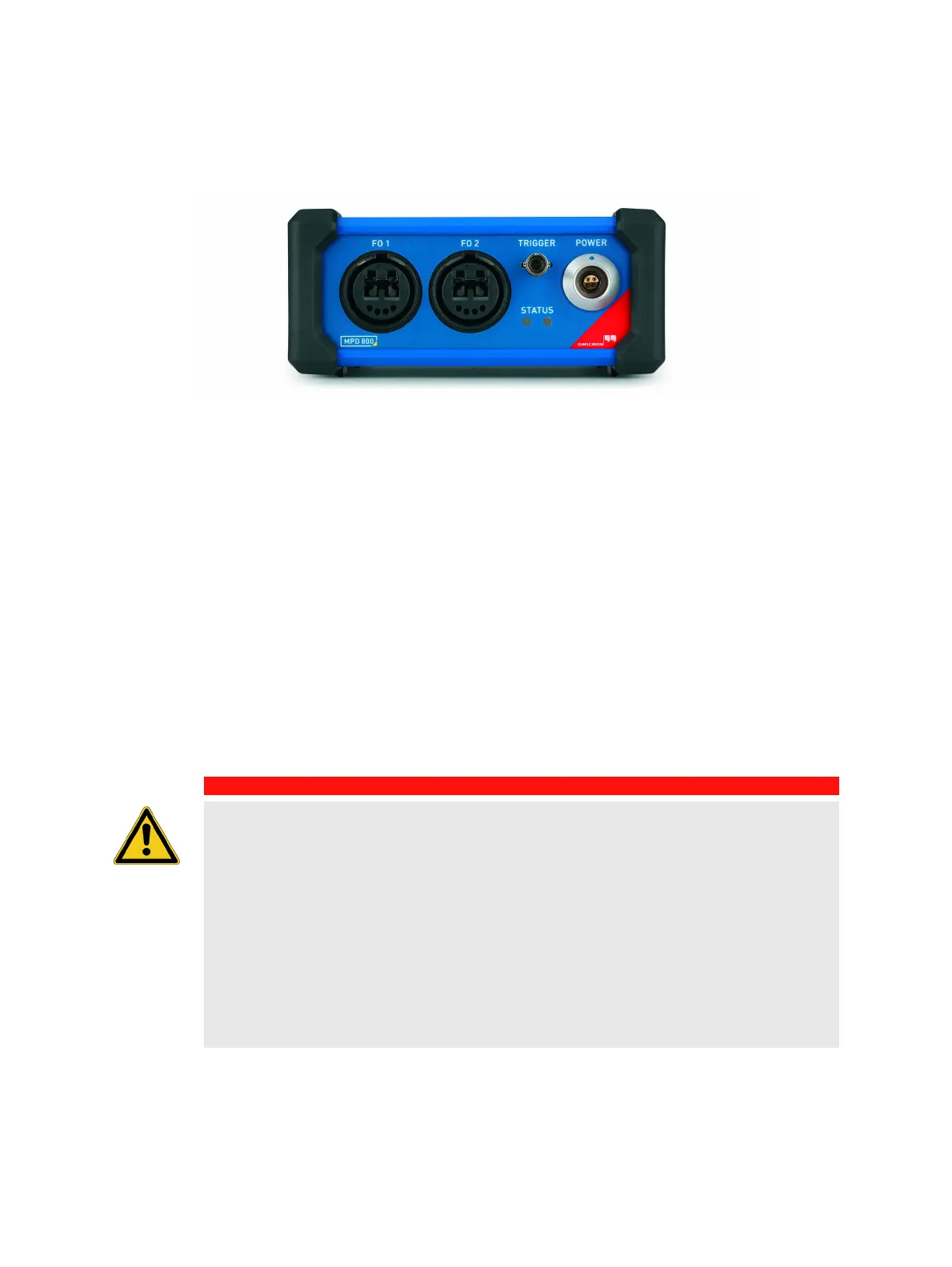
Front panel connections
Figure 2-2: MPD 800 acquisition unit front panel
Two fiber-optic duplex LC-connectors FO 1 and FO 2 are located on the front panel. The connectors
FO 1 and FO 2 are used to connect the MPD 800 acquisition unit to MCU2 or to connect an additional
MPD 800 acquisition unit in a daisy chain via fiber-optic cables provided by OMICRON. The protocol
used for these fiber connections is proprietary and might therefore not be routed through existing fiber
networks. Both fiber-optic connectors are equivalent in function. Therefore it doesn’t matter which port
is used for connecting MCU2 or the subsequent MPD 800 acquisition unit respectively.
Also an additional fiber-optic connector TRIGGER is located on the front panel. The TRIGGER output is
used to connect the OMICRON PDL 650 or other equipment which can be triggered by optical pulses.
Consult the corresponding manuals for further information.
The POWER connection socket is used for the power supply which is connected to RBP1.
For description of the indicators (named STATUS on the front panel) see section "Indicators" on
page 16.
This product contains one or more eye-safe lasers of class 1.
DANGER
Death or severe injury caused by high voltage or current
► Do not under any circumstances use metallic re-enforced conductive fiber-optic
cables.
► Always use only fiber-optic cables supplied by OMICRON.
► Always use dry and clean fiber-optic cables to avoid or minimize leakage currents.
► Make sure that the cables have ground contact to avoid leakage current to MCU2.
► Eliminate the risk of leakage currents.
► Observe the appropriate distance to high-voltage area (see 1.2.1 "Safety standards"
on page 6).
► Observe the minimum creeping distance on the fiber-optic cable (IEC 61010-1).