OMICRON 41
MPD 800 measurement system
7. Select the Coupling Unit from the drop-down list box (see also Figure 2-22).
Figure 2-25: Selection of the Coupling Unit
Note: If an external sensor or coupling device:
• inverts the AC signal, click on Normal to invert the current flow.
• adds a phase shift/offset to the signal, enter the Phase Offset in the input box.
Figure 2-26: Correction of the AC Signal Polarity and Phase Offset
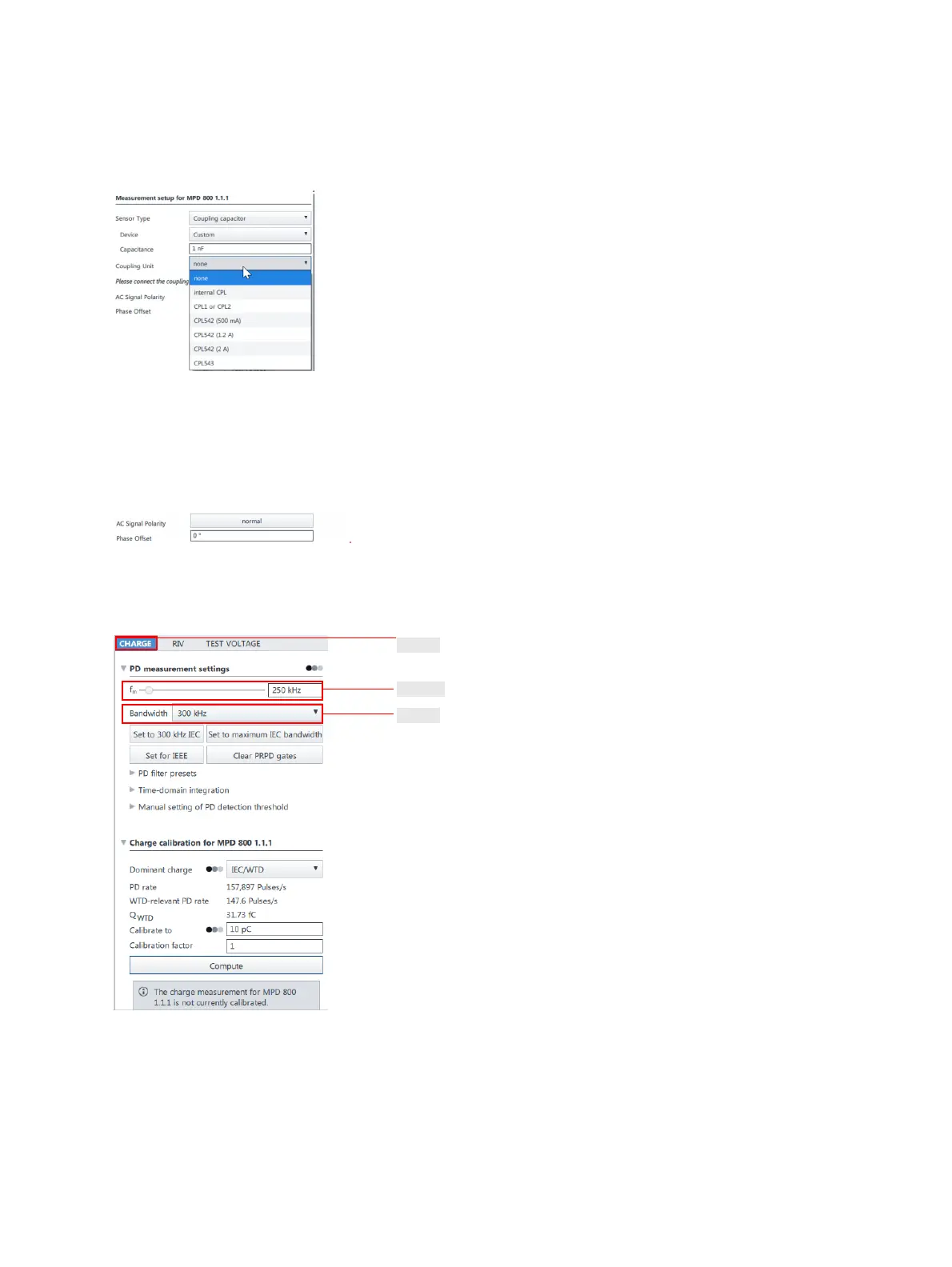
8. The CHARGE subtab in the main measurement window is selected by default.
Figure 2-27: CHARGE subtab
9. Select the bandwidth of the PD measurement filter in the Bandwidth drop-down list box.
10.Select or enter the center frequency (f
m
) of the PD measurement filter.
Note: Clicking the Set to 300 kHz IEC, Set to maximum IEC bandwidth or Set for IEEE button, the
bandwidth and center frequency (f
m
) are set to standard compliant values.