OMICRON 45
MPD 800 measurement system
4. Click the Compute button. Now the high voltage is shown in the measured value area.
5. Select the next channel or unit (for example, MPD 800 1.1.2) for further Test Voltage calibration and
follow the instructions from step 1. on page 44.
Now, the MPD 800 system is configured and the high-voltage setup is calibrated. The MPD 800
acquisition unit is ready for PD testing and you can conduct the measurement.
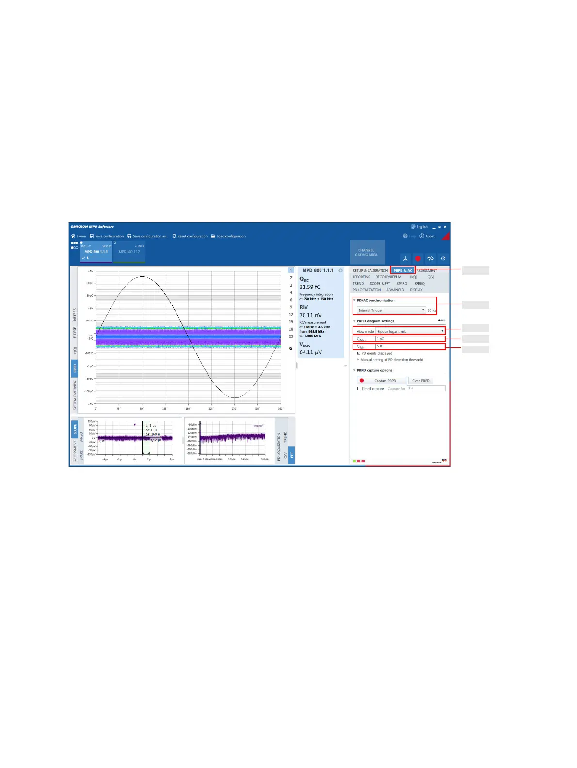
PRPD & AC tab
In the PRPD & AC tab, the synchronization source for the PRPD pattern is selected and the PRPD
diagrams are scaled to the expected PD level.
Figure 2-31: PRPD & AC view
1. Select the PRPD & AC tab.
2. Select the test voltage synchronization source for generating phase-resolved partial discharges
(PRPDs) in the PD/AC synchronization drop-down list box.
3. Select the view mode for the PRPD pattern (unipolar, bipolar, linear or logarithmic) in the View mode
drop-down list box.
4. In the next step, scale the PRPD view: Enter the maximum expected charge value in the Q
Max
input
box.
5. Enter the minimum expected charge value which is at the edge of the background noise level in the
Q
Min
input box, so that only a few pulses are detected.
Step 1.
Step 2.
Step 3.
Step 4.
Step 5.