MX2 Quick Start Guide 11
INSTALLATION
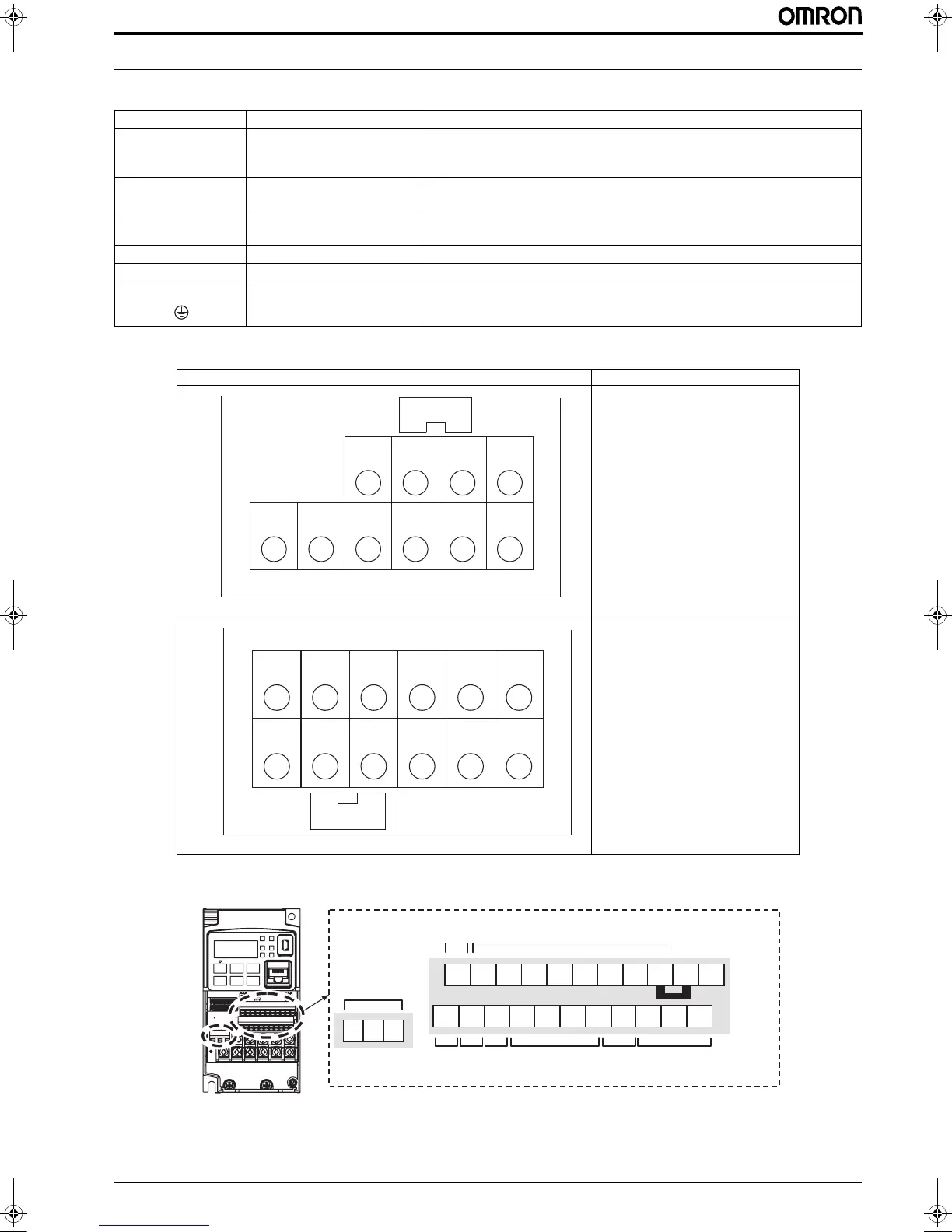
2.5 Power wiring
2.6 Control wiring
Terminal name Purpose
Details
R, S, T
(L1, L2, L3)
Main circuit, power supply
Single phase 200-240V (Connect to L1 and N terminals)
Three phase 200-240V
Three phase 380-480V
U, V, W
(T1, T2, T3)
Motor output
Three phase motor connection (IM, PM)
+1, + DC reactor
Remove the link and install DC reactor for improvement of harmonics level and
power factor
RB Extrenal brake resistor
An external braking resistor is connected.
+, - Regeneration braking unit
For connection of external regeneration braking unit
G Earth
Earthing terminal.
Terminals arrangment Applicable models
3G3MX2-AB001 to AB022
3G3MX2-A2001 to A2037
3G3MX2-A4004 to A4040
3G3MX2-A2040 to A2150
3G3MX2-A4055 to A4150
5%
7/ 87 97 :76/5/
WROLQN
5HPRYHIRU'&
UHDFWRUFRQQHFWLRQ
5%
7/ 87 97 :76/5/
WROLQN
5HPRYHIRU'&
UHDFWRUFRQQHFWLRQ
Analog
output
Logic inputs
Logic
output
Short bar
PLC
Analog
input
Pulse
Train
input
Pulse
Train
onput
RS485
comm.
RS485
comm.
P24 1 L3 25 46SN 7
12 11 AM CM2 OI LH OEASP EO
AL2 AL1 AL0
Relay
contacts
I129E-EN-02+MX2+QuickStartGuide.book Seite 11 Mittwoch, 7. November 2012 1:54 13

 Loading...


