MX2 Quick Start Guide 35
PARAMETER LIST
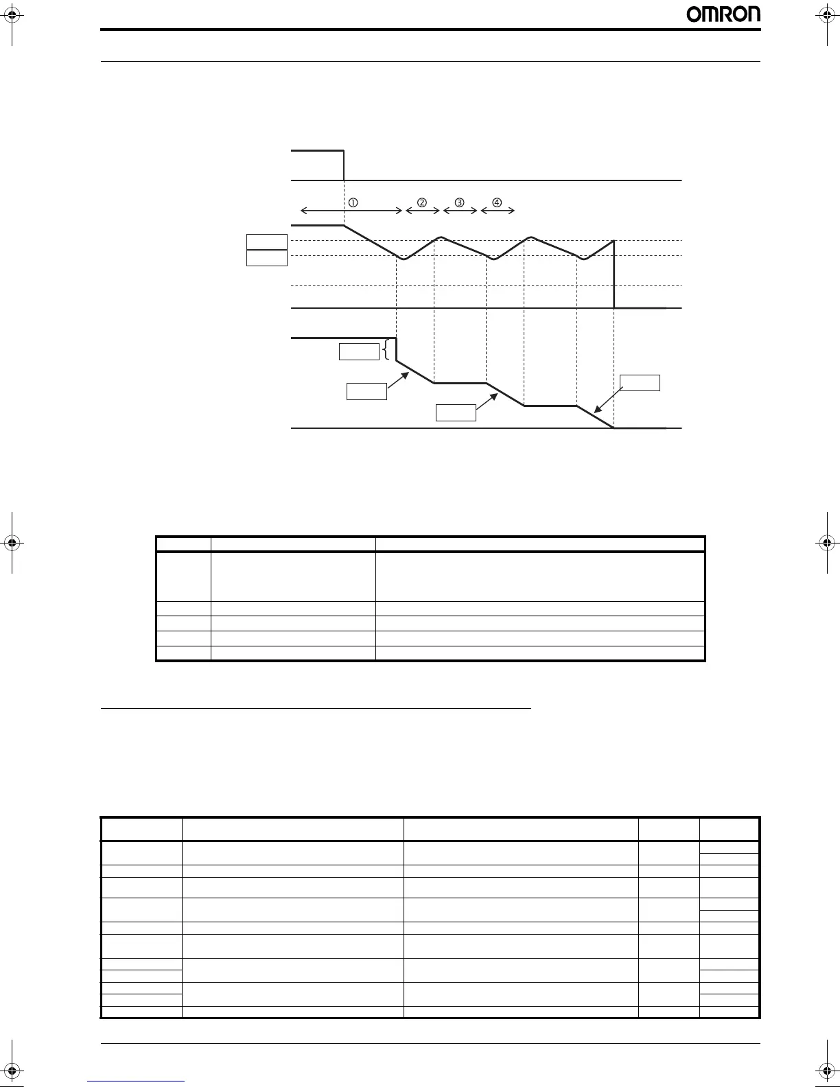
3.23 Controlled stop at power loss
This function is intended to achieve a controlled stop and avoid free-running of the motor when power is lost during run mode.
Inverter controls the internal DC bus voltage while decelerating the motor using the regenerative energy to keep the DC bus at a
level that allows to reduce the motor speed and avoid a long coasting time. Next diagram shows how the function works:
When the DC voltage of the inverter goes down to b051 level, inverter decrease the output frequency by a amount set in b054 to
force the motor to regenerate energy that is used to increase the DC bus value. After this the deceleration continue at the rate set
in b053 until the upper limit b052 is reach were the deceleration ramp stops until the DC bus drops again. This operation is repa-
ted until the motor is totally stopped or there is not enough regeneration from the motor and the DC bus goes below the under-
voltage level.
4 PARAMETER LIST
The PDU (Process Data Unit) register number are addressed starting at zero. Therefore register numbered “0012h” addressed as
“0011h”. Register address value (transmited on Modbus line) is 1 less than the Register number of the table
4.1 Parameter group D: Monitors
Parameter Parameter name Description
b050 Controlled deceleration on power loss 00 Trips
01 Decelerates to a stop
02 Decelerates to a stop with DC bus voltage controlled
03 Decelerates to a stop with DC bus voltage controlled, then restart
b051 DC bus voltage trigger level of ctrl. decel. Setting of DC bus voltage to start controlled decel. operation. Range is 0.0 to 1000.0
b052 Over-voltage threshold of ctrl. decel. Setting the OV-LAD stop level of controlled decel. operation. Range is 0.0 to 1000.0
b053 Deceleration time of ctrl. decel. Range is 0.01 to 3600.0
b054 Initial freq. drop of ctrl. decel. Setting of initial freq. drop. Range is 0.0 to 10.0 Hz
Function code Function name Monitoring and setting items Units Modbus
Register No.
d001 (32-bits) Output frequency monitor 0 to 40000(100000) 0.01 [Hz] 1001h
1002h
d002 Output current monitor 0 to 65530 0.01 [A] 1003h
d003 Rotation direction minitoring 0: Stopping, 1: Forward rotation,
2: Reverse rotation
0.1 [Hz] 1004h
d004 (32-bits) Process variable (PV), PID feedback monitoring 0 to 1000000 0.1 1005h
1006h
d005 Intelligent input terminal status 2^0: Terminal 1 to 2^6: Terminal 7 1 bit 1007h
d006 Intelligent output terminal status 2^0: Terminal 11 to 2^1: Terminal 12/
2^2: Relay Terminal
1 bit 1008h
d007 (high) Scaled output frequency monitor 0 to 4000000(10000000) 0.01 1009h
d007 (low) 100Ah
d008 (high) Actual-frequency monitor -100000 to +100000 0.01 [Hz] 100Bh
d008 (low) 100Ch
d009 Torque command monitor -200 to +200 1 [%] 100Dh
Power
DC bus voltage
Output frequency
b052
b051
Under-voltage
level
OFF
b054
b053
b053
b053
I129E-EN-02+MX2+QuickStartGuide.book Seite 35 Mittwoch, 7. November 2012 1:54 13

 Loading...


