A-29
Appendices
CJ-series PROFIBUS Master Unit Operation Manual for NJ-series CPU Unit (W509)
A-7 Slave Diagnostics Message
App
Consecutive bytes contain the diagnostics flags for Module 8 through 15, 16 through 23, etc.
The Module related diagnostics information is usually followed by the Channel related diagnostics,
which contain the actual diagnostics data per module.
Channel Related Diagnostics
Channel related diagnostics contain diagnostics information related to a specific channel in a config-
ured I/O module, e.g. over peak current detected on current input channel 2, module 0.
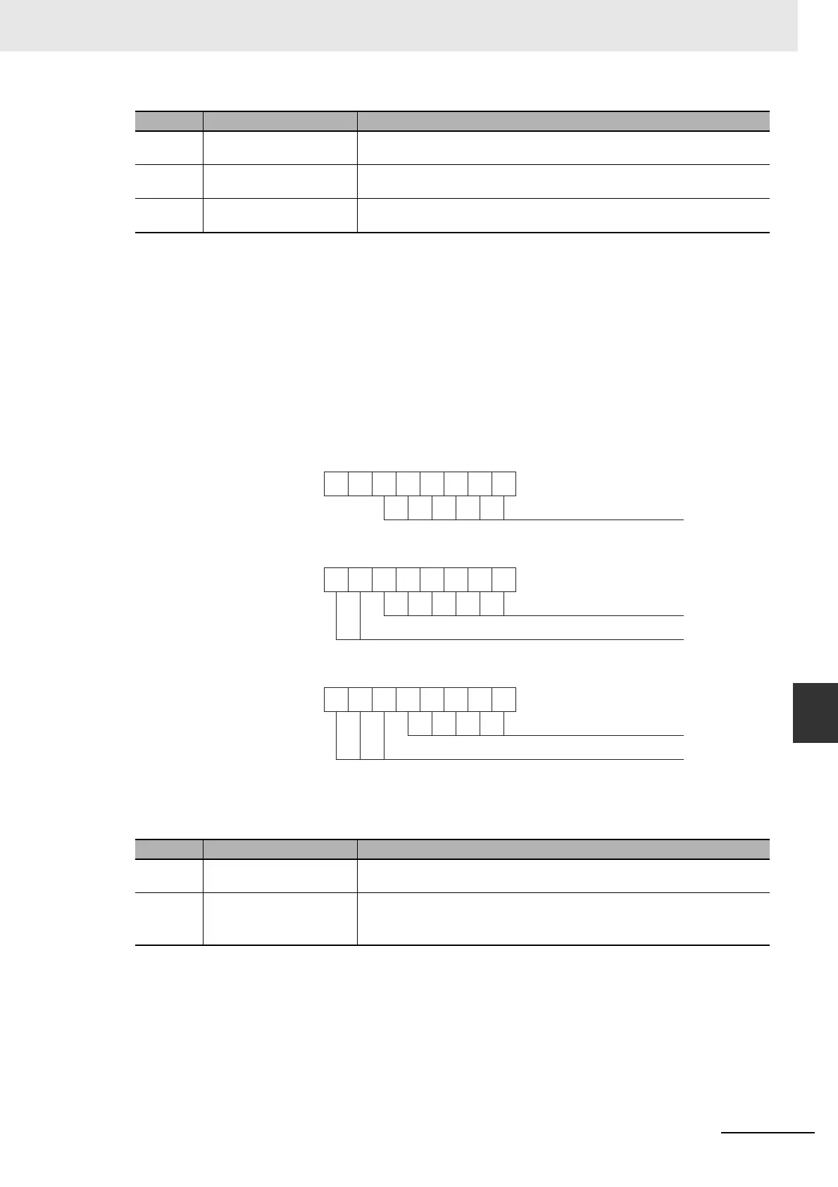
The Channel related diagnostics information entry in the diagnostics message, always consists of
three bytes, which are outlined below. From these bytes the actual event can be deducted.
Module Identifier Byte
05 Module 5 Diagnostics When set, this bit indicates that there is Diagnostics information pending related
to configuration module 5.
06 Module 6 Diagnostics When set, this bit indicates that there is Diagnostics information pending related
to configuration module 6.
07 Module 7 Diagnostics When set, this bit indicates that there is Diagnostics information pending related
to configuration module 7.
Bit Name Description
00 to 05 Module number These bits contain the number of the configuration module, to which the channel,
reporting diagnostics belongs. The module number ranges from 0 to 63.
06 to 07 Reserved Fixed to 10.
The combination of bit 6 and 7 indicate the type of diagnostics, i.e. 10 indicates
Channel related diagnostics data.
Bit Name Description
1 0
76543210
Module number
Module Identifier byte
Channel Identifier byte
76543210
Channel number
I/O type
76543210
Error type number
Error Identifier byte
Channel size type

 Loading...


