Name Model Description Remark
Parallel I/O
cable for
Connector-
T
erminal
Conversion
Unit
XW2Z-££
£EE
Specialized for FH series
Cable length: 0.5 m, 1 m,
1.5 m, 2 m, 3 m, 5 m
Min. bending radius: 83.2
mm
• T
wo these cables are needed to use all I/O signals.
• One side of this cable is flat cable and another side
of it is a connector.
• Connect the parallel I/O cable with securing the
minimum bending radius and more.
• Cable length is set to £ in the model number. (050
= 0.5 m, 100 = 1 m, 150 = 1.5 m, 2 = 2 m, 300 = 3
m, 500 = 5 m)
• Connectable Connector-Terminal Block Conversion
Unit: XW2R-£34GD-T
Connector-
T
erminal
Conversion
Unit for
general-
purpose
XW2R-
£34GD-T
-
The following is set to £ in the model number
.
For details, refer to the XW2R Series catalog (Cat. No.
G077).
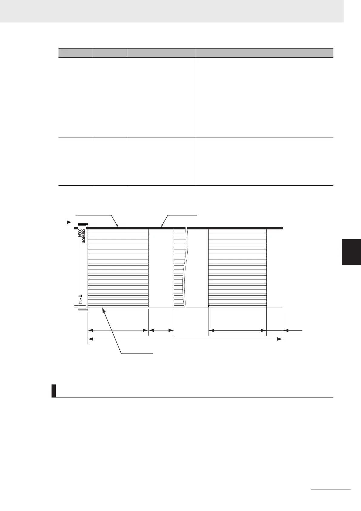
XW2Z-S013-£
Unfused part
Cable mark
L
*1
1
2
33
34
(70) (70) (15)(30)
Fused part
*1. Cable is available in 2 m/5 m.
Pin Layout
Terminal assignments and signal names should be set according to the FH Sensor Controller's opera-
tion mode settings. Verify that the wiring conforms to that.
6 I/O Interface
6-5
FH Series Vision System Hardware Setup Manual for 3D Robot Vision (Z436-E1)
6-1 Parallel Interface
6
6-1-1 FH-5050

 Loading...


