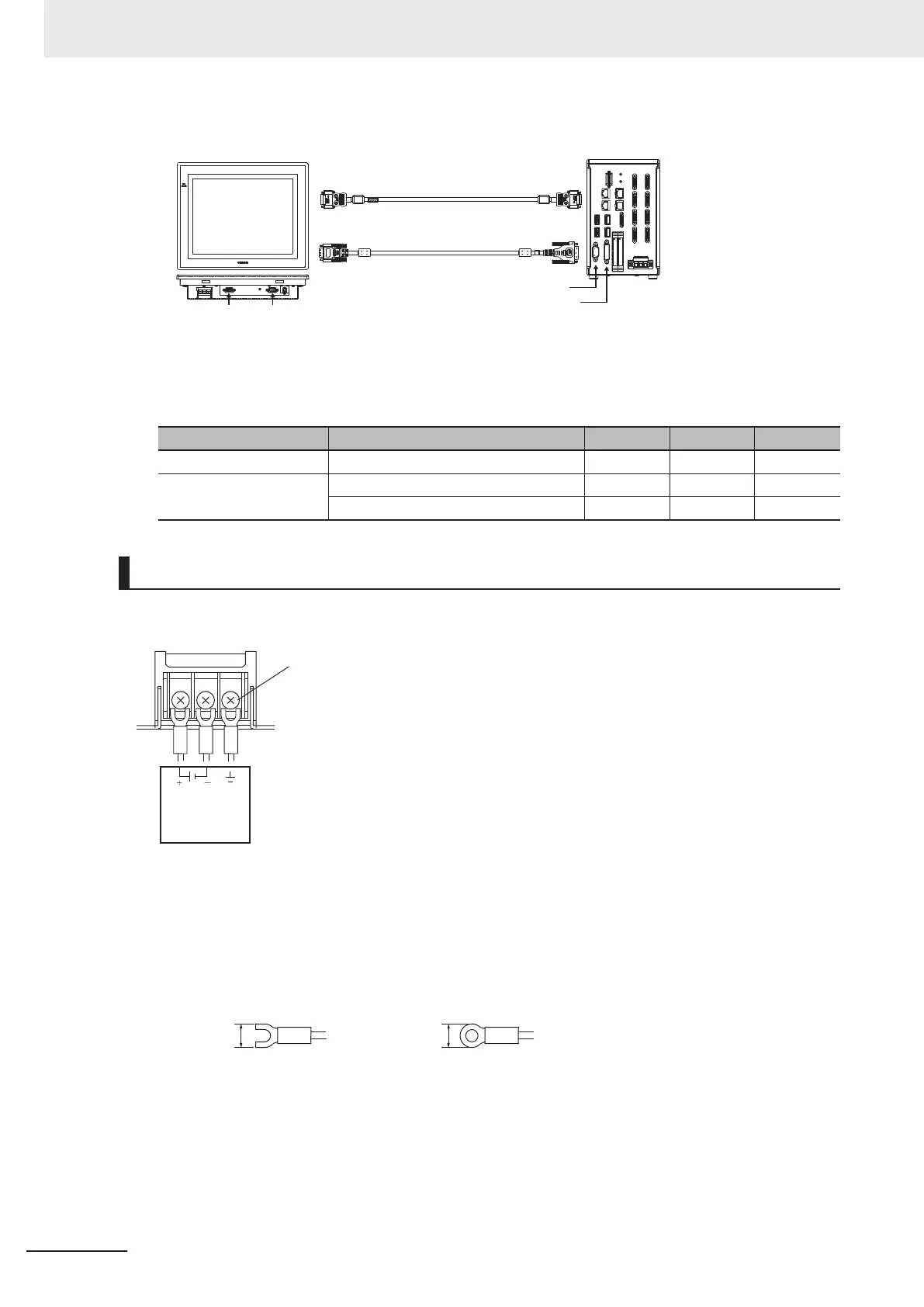
RS-232C Connection (Cable Length Up to 10 m)
FH controller
FH-MT12
DVI-AD-Sub
nalog RGB
DVI-I
RS-232C
Monitor cable: FH-VMDA
RS-232C
Touch panel cable(RS-232C):
XW2Z-PP-1
A video signal cable and an operation signal cable are required to connect the Touch Panel Moni-
tor
.
Signal Cable 2 m 5 m 10 m
Video signal DVI-Analog Conversion Cable OK OK OK
Touch panel operation
signal
USB Cable OK OK -
RS-232C Cable OK OK OK
Wiring
The power terminal block for the Touch Panel Monitor is located on the back of it.
Connect a power supply of 24 VDC there.
M4
Power supply
24 VDC
24 VDC
Recommended model
by OMRON:
S8VS-03024
• Wire the power supply wires as short as possible. (Max.2 m)
• If UL's certification is required, use a UL class II power supply.
• Use the cables and crimping terminals with the specified dimensions.
Do not directly connect an electric wire that is simply twisted to the terminal block.
- Recommended wire size: AWG 13 to 22 (0.326 to 2.62 mm
2
)
- Terminal screw: M4 (Tightening torque: 1.0 N•m)
- Crimping Terminal
3 Configuration
3-22
FH Series Vision System Hardware Setup Manual for 3D Robot Vision (Z436-E1)

 Loading...


