2-6
INSTALLATION AND
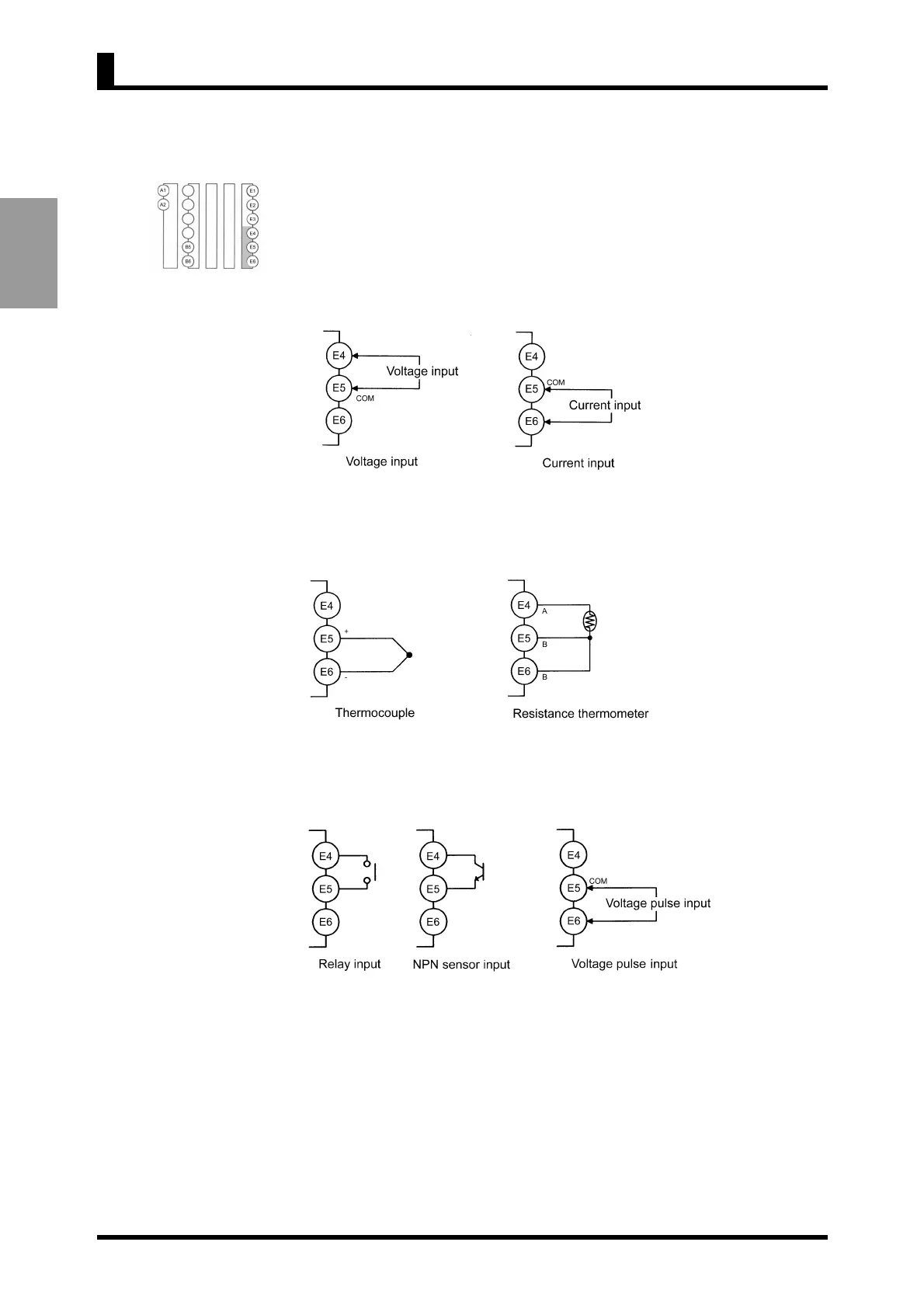
CONNECTION
Input
Input signals to be measured.
Input that can be measured by each model is as follows:
Voltage/Current (K3MA-J)
According to the input type, connect input devices to terminals shown below.
Be sure not to exceed the absolute maximum rating even for a moment.
Temperature (K3MA-L)
According to the input type, connect input devices to the terminals E4-E6.
Pulse signals (K3MA-F)
According to the types of signals to be input, connect input devices as shown below.
For the PNP sensor input connection, refer to "1-3 I/O Circuit".
The input equipment connected to these terminals must meet the following
conditions.
Transistor: ON residual voltage: 2.5 V max.
OFF leakage current: 0.1 mA max.
Current leakage with Transistor turned ON: 15 mA min.
Relay: Min. load current: 5 mA max.
Voltage pulse:H Level: 4.5 to 30 V
L Level: 0 to 2 V
Input impedance: 10KΩ
CHAPTER 2 INSTALLATION AND CONNECTION
 Loading...


