118
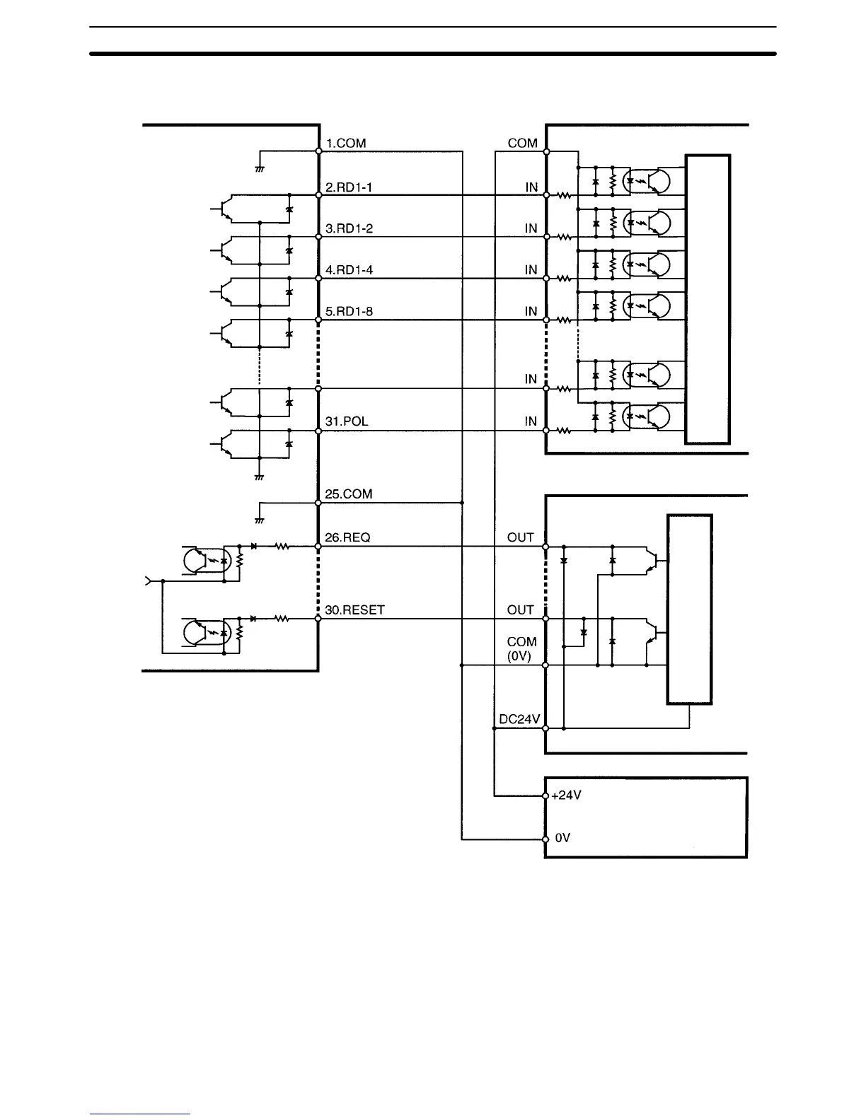
Connection Example
Frequency/Rate Meter
SYSMAC Programmable Controller
DC Input Unit
Internal circuit
Transistor Output Unit
Internal circuit
DC power supply
23.DSV
240 Ω
240 Ω
240 Ω
240 Ω
+5V
Note 1. Connect RD2-1 through RD2-4, RD3-1 through RD3-4, RD4-1 through
RD4-4, and RD5-1 through RD5-4 in the same way as RD1-1 through
RD1-4.
2. Connect the RUN and OVER signals if they are used as status data.
Signals When the HOLD signal is ON, the measurement operation stops and the pro-
cess value input effective immediately before the HOLD signal is retained.
When the RESET signal is ON, the maximum and minimum values are set to the
process value.
The OVER signal is ON when the input value is not within the display range.
Connectors Section 7-1