4 Designing the Power Supply System
4 - 6
NX-series NX1P2 CPU Unit Hardware User’s Manual (W578)
The following must be studied when designing the power supply system to CPU Rack.
• The NX Unit power supply and I/O power supply systems must be designed and then the design con-
ditions for both must be confirmed.
• The external power supplies (i.e., Unit power supply and I/O power supplies) must be selected.
I/O Power
Supply
Connection
Unit
This NX Unit is used when there are not enough I/O power supply terminals for the connected
external devices that are connected to NX Units such as Digital I/O Units and Analog I/O Units.
*1. Wire colors have been changed according to revisions in the JIS standards for photoelectric
and proximity sensors. The colors in parentheses are the wire colors prior to the revisions.
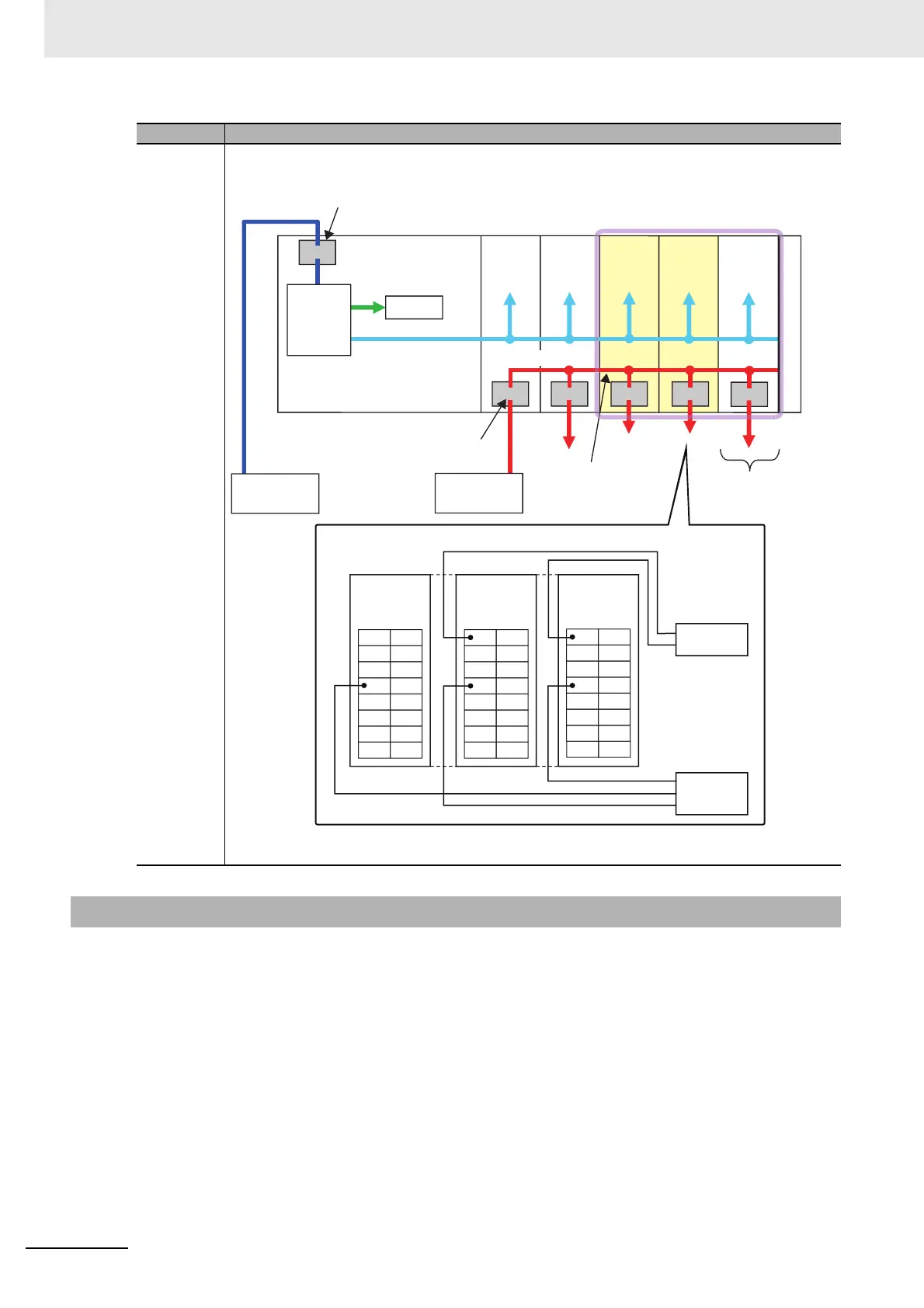
4-1-3 Design Concepts for Power Supply to the CPU Rack
Unit name Function
End
Cover
Not enough I/O
power supply
terminals
I/O power supply is not
separated at the I/O Power
Supply Connection Units.
NX Unit NX Unit
Additional
I/O Power
Supply
Unit
I/O Power
Supply
Connec-
tion Unit
I/O Power
Supply
Connec-
tion Unit
NX-series NX1P2
CPU Unit
Unit power supply terminals
Internal
power
supply
circuit
Internal
circuits
NX Unit power supply
Unit power
supply
(24 VDC)
I/O power supply
(24 VDC, etc.)
I/O power supply
terminals
I/O power supply
A1
A8
B1
B8
A1
A8
B1
B8
A1
A8
B1
B8
Brown (White)
Blue (Black)
Black (White)
Brown (Red)
Blue (Black)
IOV
IOV
IOV
IOV
IOV
IOV
IOV
IOV
IOV
IOV
IOV
IOV
IOV
IOV
IOV
IOV
IOG
IOG
IOG
IOG
IOG
IOG
IOG
IOG
IOG
IOG
IOG
IOG
IOG
IOG
IOG
IOG
1
9
7
5
3
13
11
15
0
8
6
4
2
12
10
14
DC Input Unit
(NPN type)
I/O Power Supply
Connection Unit
(IOV terminals: 16)
I/O Power Supply
Connection Unit
(IOG terminals: 16)
Two-wire sensor
*1
(limit switches, etc.)
Three-wire sensor with
NPN output
Three-wire sensor
*1
(photoelectric sensor,
proximity sensor, etc.)
Example of NPN type
○

 Loading...


