5 - 35
5 Installation and Wiring
NX-series NX1P2 CPU Unit Hardware User’s Manual (W578)
5-3 Mounting Units
5
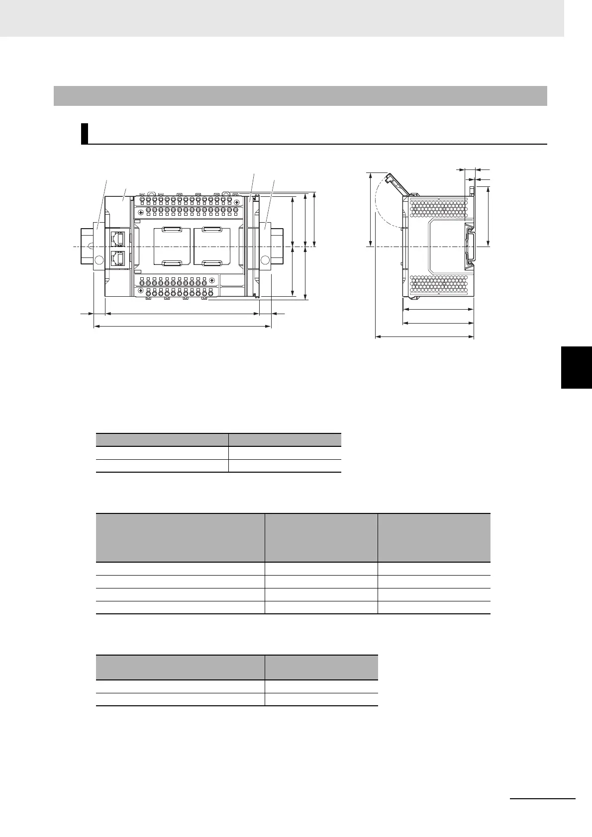
5-3-13 Assembled Appearance and Dimensions
W: CPU Unit width (Includes the End Cover.)
• Unit width
• DIN Track dimension
• End Plate dimension
5-3-13 Assembled Appearance and Dimensions
Installation Dimensions
Model Unit width [mm]
NX1P2-140DT 154
NX1P2-9024DT 130
DIN Track model
(A)
DIN Track dimension
(B)
Dimension from the
back of the Unit to the
back of the DIN Track
PFP-100N 7.3 mm 1.5 mm
PFP-50N 7.3 mm 1.5 mm
NS 35/ 7,5 PERF 7.5 mm 1.7 mm
NS 35/ 15 PERF 15 mm 9.2 mm
End Plate model
(C)
End Plate dimension
PFP-M 10 mm
CLIPFIX 35 9.5 mm
(When DIN Track mounting hook
is unlocked)
96.3
(Memory Card cover maximum
range of motion)
Unit: [mm]
59.7
50 50
5353
54.5
71
(A)
(C)
(B)
(Memory Card cover maximum range of motion)
70.5
72.5
W
W + (C) + (C)
End Plate
CPU Unit
End Cover
Center line
of DIN
Track
End Plate
(C)
 Loading...


