3 Configuration Units
3 - 10
NX-series NX1P2 CPU Unit Hardware User’s Manual (W578)
The terminal blocks on the CPU Unit are removable screwless clamping terminal blocks that allow you
to easily connect and remove the wiring.
There are the input terminal block and output terminal block.
This section provides the part names and functions of the terminal blocks, the terminal arrangement of
the input and output terminal blocks, and other information.
Refer to 5-4-8 Wiring to the CPU Unit Terminal Block on page 5-45 for the wiring procedure.
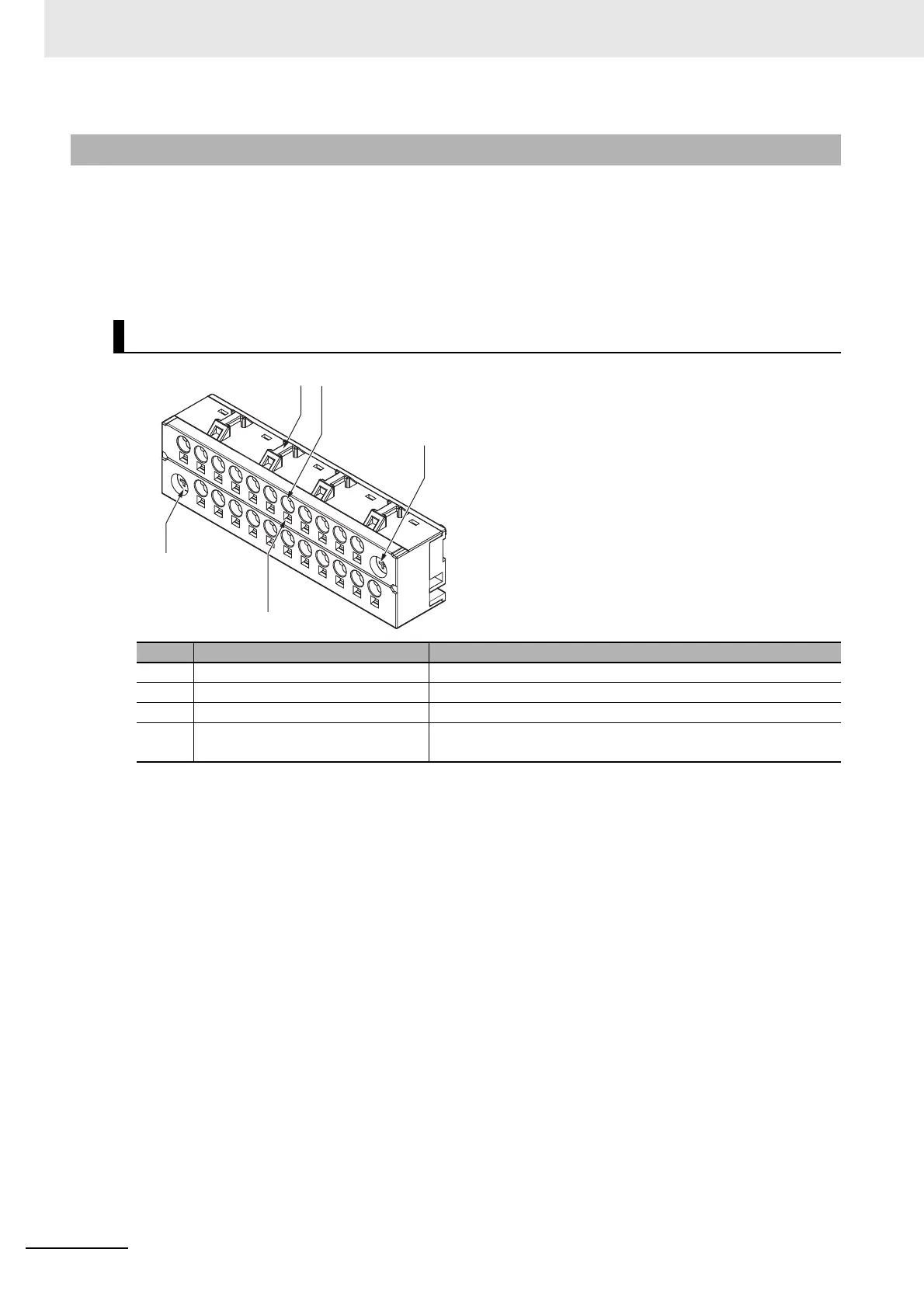
3-1-4 Terminal Blocks
Terminal Block Part Names and Functions
Letter Name Function
A Hole for securing wires Pass a cable tie through this hole for securing the wires.
B Terminal hole The wire is inserted into this hole.
C Screw for securing Screw for securing the terminal block on the CPU Unit.
D Release hole Insert a flat-blade screwdriver into this hole to connect and
remove the wire.

 Loading...


