3 - 11
3 Configuration Units
NX-series NX1P2 CPU Unit Hardware User’s Manual (W578)
3-1 CPU Units
3
3-1-4 Terminal Blocks
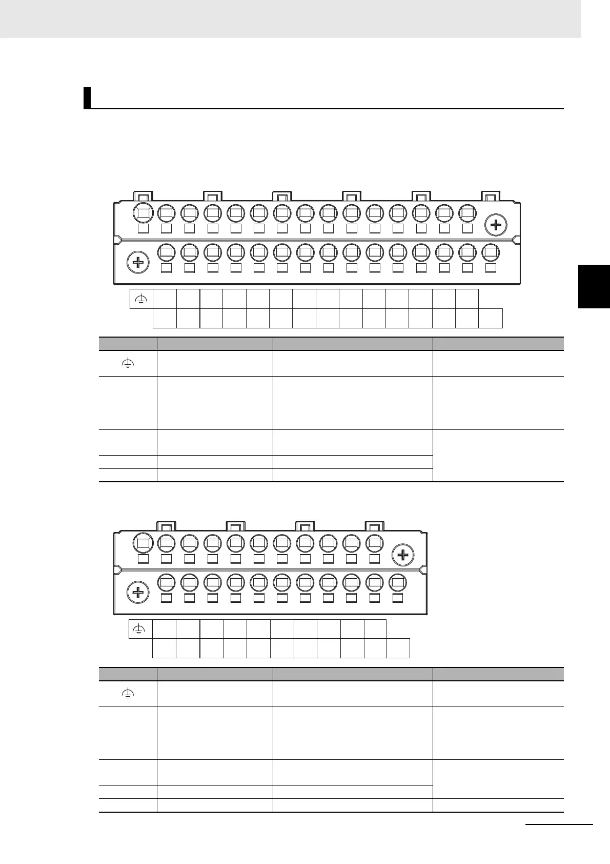
Terminal Arrangement
The description is given for each CPU Unit model.
a) NX1P2-140DT
b) NX1P2-9024DT
Input Terminal Block
Symbol Terminal name Description Reference
Functional ground termi-
nal
The functional ground terminal. Con-
nect the ground wire to the terminal.
5-4-5 Grounding on page
5-41
+/- Unit power supply termi-
nals
These terminals are connected to the
Unit power supply.
The + terminals and - terminals are
internally connected to each other.
5-4-1 Wiring the Unit Power
Supply on page 5-39
COM Common terminal Common terminal for the input cir-
cuits
Input Specifications on page
3-12
00 to 15 Input terminals General-purpose input A
16 to 23 Input terminals General-purpose input B
Symbol Terminal name Description Reference
Functional ground termi-
nal
The functional ground terminal. Con-
nect the ground wire to the terminal.
5-4-5 Grounding on page
5-41
+/- Unit power supply termi-
nals
These terminals are connected to the
Unit power supply.
The + terminals and - terminals are
internally connected to each other.
5-4-1 Wiring the Unit Power
Supply on page 5-39
COM Common terminal Common terminal for the input cir-
cuits
Input Specifications on page
3-12
00 to 13 Input terminals General-purpose input A
NC NC Do not connect anything. ---
+-
-+
COM
00
17
18
15
16
13
14
11
12
09
10
07
08
05
06
03
04
01
02
19
20
21
22 23
NC
13
NC
11
12
09
10
07
08
05
06
03
04
01
02
COM
00
-
-
+
+

 Loading...


