4 - 13
4 Designing the Power Supply System
NX-series NX1P2 CPU Unit Hardware User’s Manual (W578)
4-3 Designing the I/O Power Supply System
4
4-3-2 Designing the I/O Power Supply from the NX Bus
The total current consumption from the I/O power supply from the NX bus is the total of the following
current consumptions.
• The current consumption from the I/O power supply that is required for the Additional I/O Power Sup-
ply Unit and for the NX Units that are connected to the Additional I/O Power Supply Unit
• The current consumption between the NX Units and the connected external devices
Calculation Example of I/O Power Supply Capacity
An example of calculating the required power supply capacity of the I/O power supply is given
below.
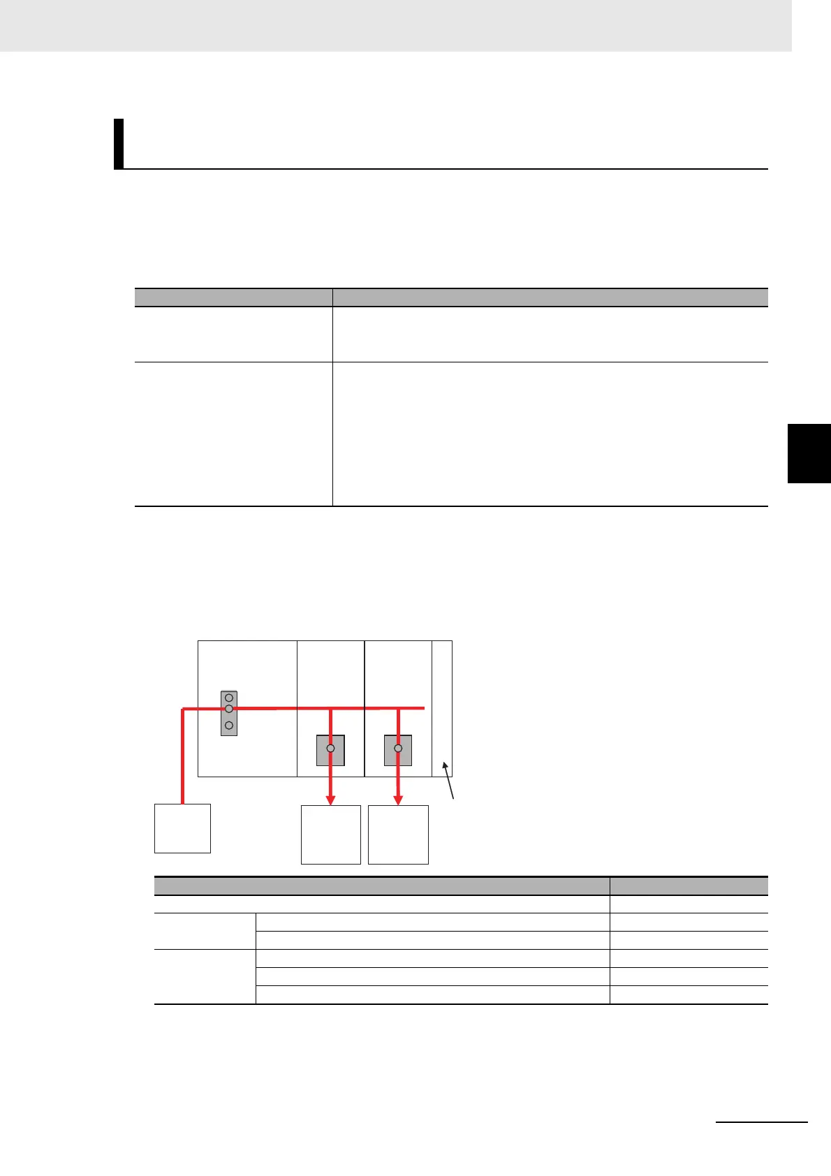
Configuration and Conditions
I/O power is supplied to the NX-ID3317 and NX-OD3121 from the NX bus.
Calculating the Total Current Consumption from the I/O Power Sup-
ply
Current consumption item Description
Current consumption from I/O
power supply
This is the current that is consumed by the internal circuits that operate on
the I/O power supply.
Specific values are given in the user’s manuals for individual Units.
Current consumption between
the NX Units and the connected
external devices
This is the current that is consumed between the NX Units and the con-
nected external devices.
For example, this is the current consumed by a Digital Input Unit to supply
power to photoelectric sensors or to turn ON the input circuits in the Digital
Input Unit.
The current consumption depends on the type of I/O circuit in the NX Unit,
the number of I/O points that are used, and the current consumption of the
connected external device. It must be calculated for each NX Unit.
Item Condition
I/O power supply voltage 24 VDC
Inputs Number of inputs used (that turn ON simultaneously) 4 points
Current consumption of connected input devices 50 mA/point
Outputs Number of outputs (that turn ON simultaneously) 4 points
Load current of connected loads 125 mA/point
Current consumption of connected output devices 50 mA/point
I/O
power
supply
(24 VDC)
Additional I/O Power
Supply Unit
NX-PF0730
End Cover
Digital Input
Unit
NX-ID3317
Connected
input
devices
Digital Output
Unit
NX-OD3121
Connected
output
devices
(loads)

 Loading...


