4 - 15
4 Designing the Power Supply System
NX-series NX1P2 CPU Unit Hardware User’s Manual (W578)
4-3 Designing the I/O Power Supply System
4
4-3-2 Designing the I/O Power Supply from the NX Bus
Voltage drop occurs in the CPU Units and NX Units due to the contact resistance at the points where
Units are connected to each other. Design the I/O power supply system to maintain the voltage specifi-
cations of the NX Unit I/O circuits and connected external devices even if the voltage of the I/O power
supply drops.
As shown in the following table, the voltage drop per Unit depends on the total current consumption
from the I/O power supply.
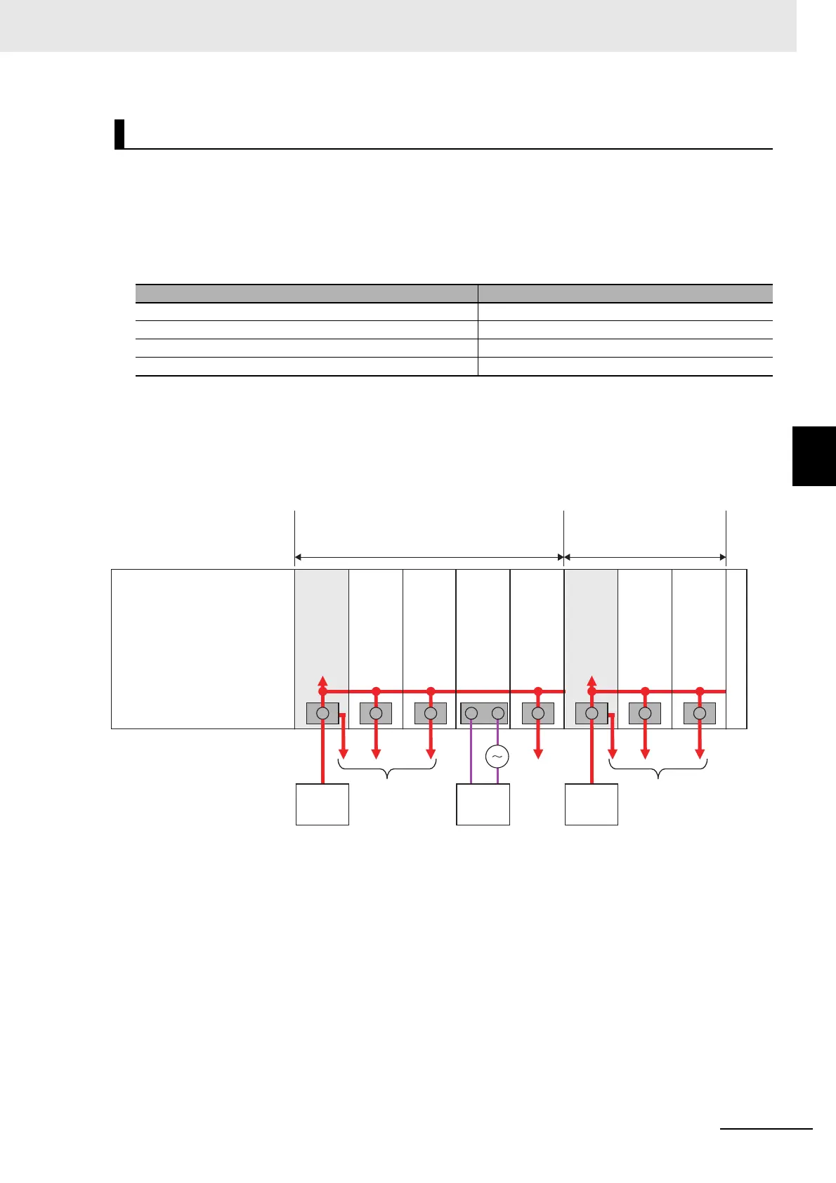
Here, the following Unit configuration example is used to show how to calculate the I/O power that is
supplied by the Additional I/O Power Supply Unit on the right of the CPU Unit. The same method can
be used to calculate the I/O power supply from an Additional I/O Power Supply Unit that is additionally
connected.
Example:
*1. The current consumption of the Additional I/O Power Supply Unit is not actually 0 A. However, a value of 0 A
is used in this calculation example.
In actual calculations, add the current consumption from the I/O power supply that is given the NX-series Data
Reference Manual (Cat. No. W525).
Outline
Find the I/O power supply voltage of the NX Unit that is the farthest from the Additional I/O Power
Supply Unit 1. In this example, the I/O power supply voltage of Unit (5) is found.
Conditions
Assume that an I/O power supply voltage of 24.00 VDC is supplied to the I/O power supply terminals
on the Additional I/O Power Supply Unit 1.
Calculating the Voltage Drop in the I/O Power Supply
Total current consumption from the I/O power supply Voltage drop per Unit
4 A 0.08 V
3 A 0.06 V
2 A 0.04 V
1 A 0.02 V
I/O power supply current consumption of each Unit
(1)
(2),(3)
(4)
(5)
: 0.0 A
*1
(
supply from the NX bus
)
: 0.5 A each
(
supply from the NX bus
)
: 0.0 A
(
supply from external source
)
: 2.0 A
(
supply from the NX bus
)
NX-series NX1P2 CPU Unit
●
Total current consumption of I/O power supply for the range
Additional I/O Power Supply Unit 1 supplies I/O power supply
(Total of (1) to (5) = 3.0 A)
● The range Additional I/O
Power Supply Unit 2 supplies
I/O power supply
Additional
I/O Power
Supply
Unit 1
Additional
I/O Power
Supply
Unit 2
NX Unit
(supply
from the
NX bus)
NX Unit
(supply
from the
NX bus)
NX Unit
(supply
from the
NX bus)
NX Unit
(supply
from the
NX bus)
NX Unit
(supply
from the
NX bus)
NX Unit
(supply
from
external
source)
End Cover
I/O power
supply
To external
devices
To external
devices
To external
devices
External
device
I/O power
supply
(24 VDC)
I/O power
supply
I/O power
supply
(24 VDC)
(1) (2) (3) (4) (5)

 Loading...


