4 Designing the Power Supply System
4 - 22
NX-series NX1P2 CPU Unit Hardware User’s Manual (W578)
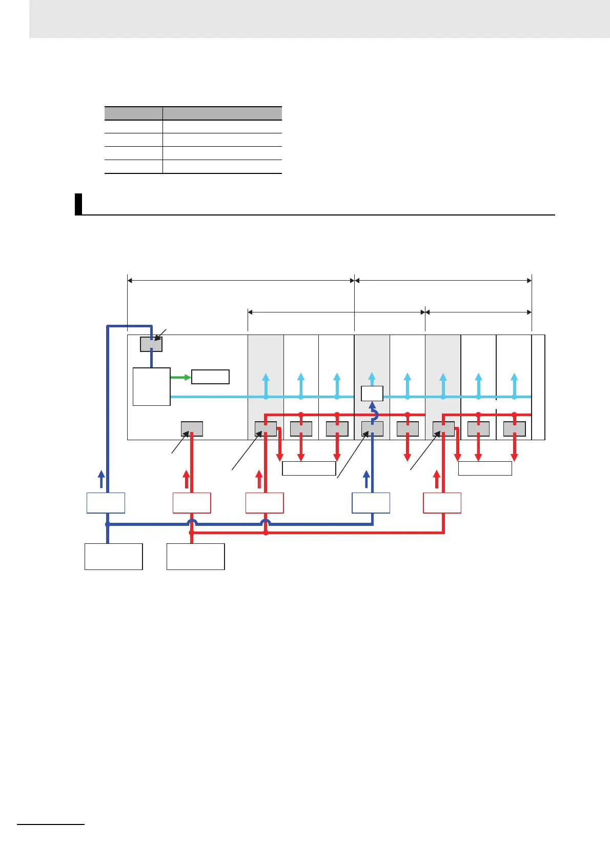
For I/O Power Supply
Install protective devices for the Unit power supply and I/O power supply in the locations that are shown
in the following figure.
However, fewer protective devices may be required when the current consumption of each block does
not exceed the rated current.
An example of this is provided below.
Current Breaking/fusing time
6 A 1 min max.
12 A 15 s max.
21 A 5 s max.
30 A 2.5 s max.
Installation Locations for Protective Devices
External devices
End
Cover
Built-in I/O
Internal
circuits
NX Unit power supply
Unit power supply
terminals
Internal
power
supply
circuit
Unit power
supply
(24 VDC)
NX-series
NX1P2 CPU
Unit
Protective
device
Protective
device
I_unit1
I_ioB
I_unit2
I_io1
I_io2
I/O power
supply
I/O power
supply
Block that the CPU Unit supplies Unit power supply.
Block that an Additional I/O
Power Supply Unit 1 supplies
I/O power supply.
Block that an Additional I/O
Power Supply Unit 2 supplies
I/O power supply.
Block that an Additional NX Unit Power Supply
Unit supplies Unit power supply.
External devices
I/O
power
supply
Unit 1
I/O
power
supply
Unit 2
Power
supply
NX power supply
Unit power
supply terminals
I/O power
supply
terminal
I/O power
supply
terminal
Cn(+V)/0Vn
terminal PNP
(sourcing)
type only
I/O power supply
(24 VDC, etc.)
Additional
NX Unit
Power
Supply Unit
○
○ ○ ○ ○ ○ ○ ○ ○ ○
Protective
device
Protective
device
Protective
device
 Loading...


