5 Installation and Wiring
5 - 8
NX-series NX1P2 CPU Unit Hardware User’s Manual (W578)
Outputs from Units, such as DC Output Units, may malfunction momentarily when the Unit power
supply is turned ON. This may cause problems in the system if the Unit power supply is turned ON after
the I/O power supply (i.e. controlled system's power supply) is turned ON. To prevent possible malfunc-
tions, configure an external circuit that prevents the power supply to the controlled system from turning
ON before the power supply to the Controller itself.
It takes approximately 20 seconds to enter RUN mode after the power supply is turned ON.
During that time, digital outputs on the CPU Rack will be OFF. The slave outputs behave
according to the setting values. Use the system-defined variables and the NX Unit device vari-
ables in the user program to confirm that I/O data communications are established before
attempting control operations. External communications are also not performed during startup.
It is possible for an output to remain ON due to a malfunction in the internal circuit of the built-in output
or output section of the Output Unit, such as a relay or transistor malfunction. Be sure to add any cir-
cuits necessary outside of the Controller to ensure the safety of the system in the event that an output
section fails to go OFF.
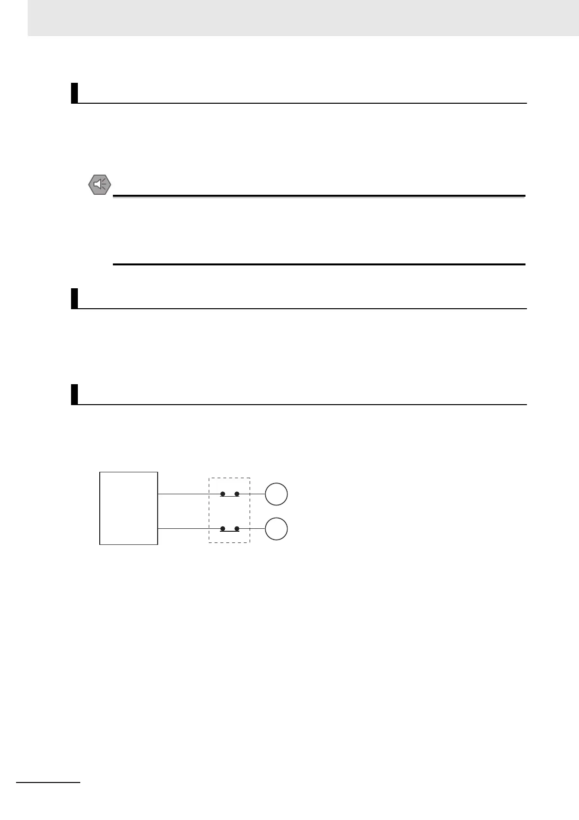
When the Controller controls an operation such as the clockwise and counterclockwise operation of a
motor, provide an external interlock such as the one shown in the following example to prevent both the
forward and reverse outputs from turning ON at the same time if required by the application.
Example:
This circuit prevents outputs MC1 and MC2 from both being ON at the same time even if both Controller
outputs ON_MC1 and ON_MC2 are ON due to a malfunction.
Order of Powering On the Controller and Controlled System
Failure of the Built-in Output or Output Section of the Output Unit
Interlock Circuits
Controller
Interlock circuit
Motor counterclockwise
Motor clockwise
MC2
ON_MC1
MC1
ON_MC2
MC1
MC2

 Loading...


