5 - 21
5 Installation and Wiring
NX-series NX1P2 CPU Unit Hardware User’s Manual (W578)
5-3 Mounting Units
5
5-3-4 Installing and Connecting NX Units
Precautions for Correct Use
• When you mount an NX Unit to the CPU Unit or when you connect NX Units to each other,
always mount the Units one at a time on the DIN Track. If you connect NX Units to each other
and attempt to mount them together to the DIN Track at the same time, the Units may sepa-
rate from each other and fall.
• When you handle a Unit, be careful not to apply stress to the pins in the NX bus connector.
If the Unit is installed and the power supply is turned ON when the pins in the NX bus con-
nector are deformed, contact failure may cause malfunctions.
• When you handle a Unit, be careful not to touch or bump the pins in the NX bus connector.
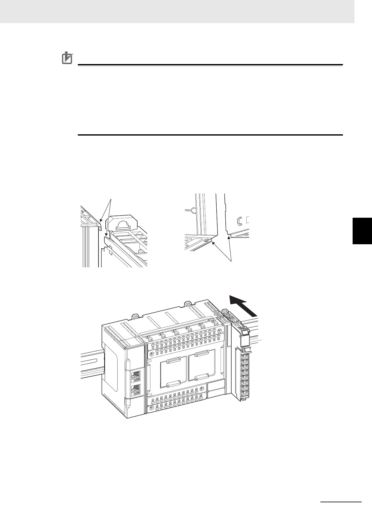
Mounting an NX Unit to the CPU Unit
Mount the NX Unit to the CPU Unit after removing the End Cover on the CPU Unit.
1 From the front of the CPU Unit, engage the Unit hookup guides on the NX Unit with the Unit
hookup guides on the CPU Unit.
2 Slide the NX Unit on the hookup guides.
3 Press the NX Unit with a certain amount of force against the DIN Track until you hear the DIN
Track mounting hook lock into place.
When you mount the NX Unit, it is not necessary to release the DIN track mounting hook on the
NX Unit.
After you mount the NX Unit, make sure that it is locked to the DIN Track.
Unit hookup guides
Unit hookup guides

 Loading...


