5 Installation and Wiring
5 - 68
NX-series NX1P2 CPU Unit Hardware User’s Manual (W578)
Precautions for Correct Use
• Use the NX1W-CIF11 (non-isolated type) only when there is no difference in electrical poten-
tial between device grounding points. Do not allow the communications distance to exceed
50 m. Connect the shield on the communications cable at both ends to the SHLD or FG ter-
minals on the RS-422A/485 terminal blocks to ground it.
• Use the NX1W-CIF12 (isolated type) if there is a difference in electrical potential between
device grounding points or for long distance communications (500 m max.). Connect the
shield on the communications cable only at the Option Board to ground it. If the shield is con-
nected at both ends of the cable when there is a difference in electrical potential, the devices
may be damaged.
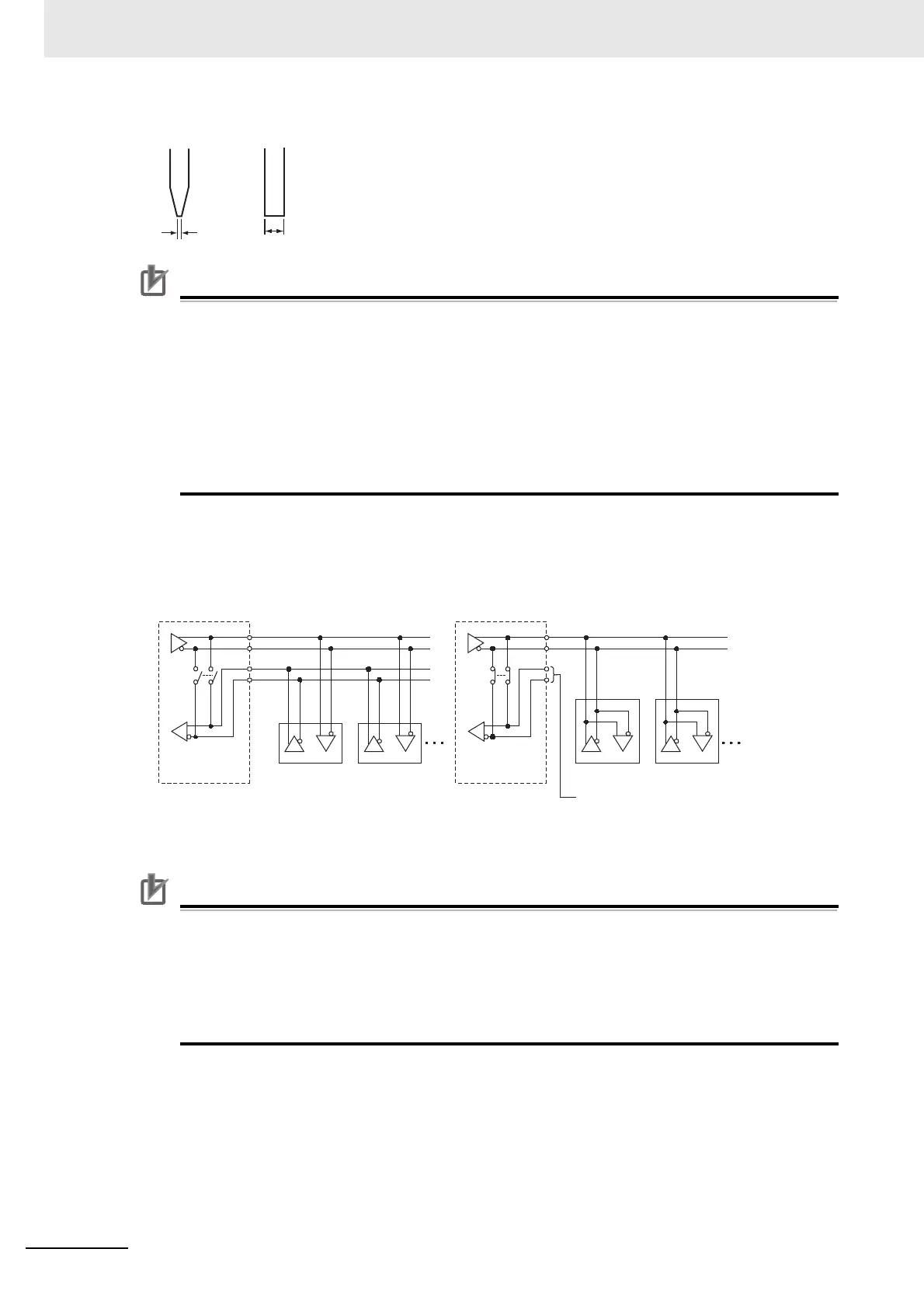
Connection Examples: Two-wire and Four-wire Transmission Circuits
The transmission circuits for two-wire and four-wire connections are different, as shown in the
following diagram.
Set a terminating resistance if it is the end of transmission circuit.
Precautions for Correct Use
• Use the same type of transmission circuit (two-wire or four-wire) for all nodes.
• Do not use four-wire connections when the two/four-wire switch on the Board is set to
two-wire.
• Always install a terminating resistance on the last RS-422A/485 node. Refer to the NX-series
NX1P2 CPU Unit Built-in I/O and Option Board User’s Manual (Cat. No. W579) for details on
the wiring example of a terminating resistance.
0.4 mm
Side Front
2.5 mm
Example of Four-wire Connections
Example of Two-wire Connections
Two/four-wire
switch
Option Board
Two/four-wire
switch
Option Board
Other Unit
Other UnitOther Unit
Other Unit
Connect to one of a pair
SDA+/- or RDA+/-.

 Loading...


