3 - 3
3 Configuration Units
NX-series NX1P2 CPU Unit Hardware User’s Manual (W578)
3-1 CPU Units
3
3-1-1 Models and Specifications
The electrical and mechanical specifications are given below.
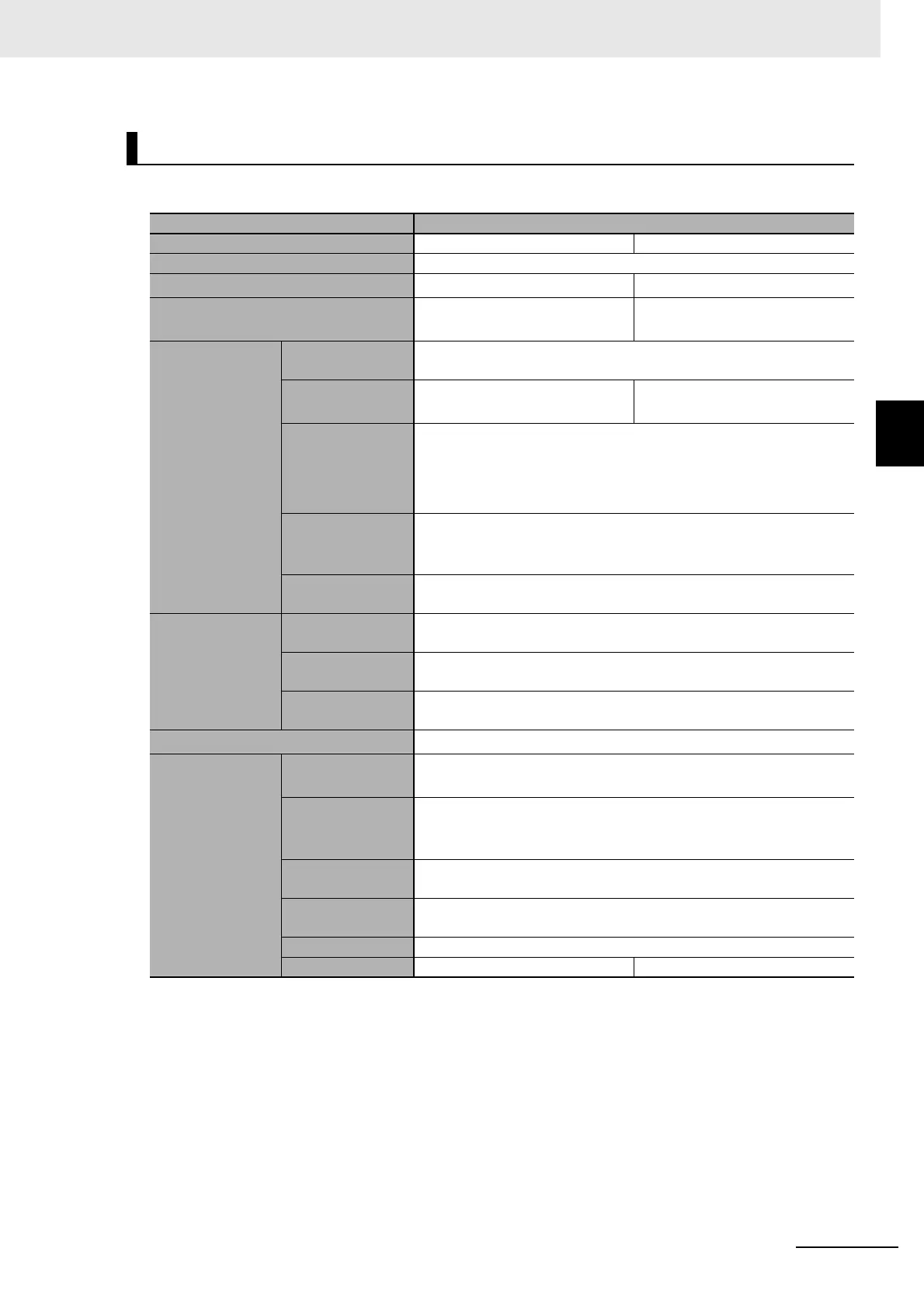
Electrical and Mechanical Specifications
Item Specification
Model NX1P2-140DT NX1P2-9024DT
Enclosure Mounted in a panel
Dimensions (mm)
*1
*1. Includes the End Cover, and does not include projecting parts.
154 × 100 × 71 mm (W×H×D) 130 × 100 × 71 mm (W×H×D)
Weight
*2
*2. Includes the End Cover. The weight of the End Cover is 82 g.
NX1P2-140DT: 650 g
NX1P2-140DT1: 660 g
NX1P2-9024DT: 590 g
NX1P2-9024DT1: 590 g
Unit power sup-
ply
Power supply
voltage
24 VDC (20.4 to 28.8 VDC)
Unit power con-
sumption
*3
*3. Includes the SD Memory Card and Option Board. The NX Unit power consumption to NX Units is not included.
NX1P2-140DT: 7.05 W
NX1P2-140DT1: 6.85 W
NX1P2-9024DT: 6.70 W
NX1P2-9024DT1: 6.40 W
Inrush current
*4
*4. The inrush current may vary depending on the operating condition and other conditions. Therefore, select
fuses, breakers, and external power supply devices that have enough margin in characteristic and capacity,
considering the condition under which the devices are used.
For cold start at room temperature:
10 A max./0.1 ms max.
and
2.5 A max./150 ms max.
Current capacity
of power supply
terminal
*5
*5. The amount of current that can be passed constantly through the terminal. Do no exceed this current value
when you use a through-wiring for the Unit power supply.
4 A max.
Isolation method
No isolation: between the Unit power supply terminal and internal cir-
cuit
Power supply to
the NX Unit power
supply
NX Unit power
supply capacity
10 W max.
NX Unit power
supply efficiency
80 %
Isolation method
No isolation: between the Unit power supply terminal and NX Unit
power supply
I/O Power Supply to NX Units
Not provided
*6
*6. When the type of the I/O power supply to NX Units you use is the supply from NX bus, an Additional I/O Power
Supply Unit is required. The maximum I/O power supply current from an Additional I/O Power Supply Unit is 4
A. Refer to 4-3 Designing the I/O Power Supply System on page 4-10 for details.
External connec-
tion terminals
Communication
connector
RJ45 for EtherNet/IP Communications × 1
RJ45 for EtherCAT Communications × 1
Screwless clamp-
ing terminal block
For Unit power supply input, grounding, and input signal: 1 (Remov-
able)
For output signal: 1 (Removable)
Output terminal
(service supply)
Not provided
RUN output termi-
nal
Not provided
NX bus connector 8 NX Units can be connected
Option board slot 21
 Loading...


