3 - 5
3 Configuration Units
NX-series NX1P2 CPU Unit Hardware User’s Manual (W578)
3-1 CPU Units
3
3-1-2 Part Names and Functions
G Unit hookup guides These guides are used to mount an NX Unit or End Cover.
H NX bus connector This connector is used to connect the CPU Unit to the NX Unit
on the right of the CPU Unit.
I Option board slot 1 (left),
Option board slot 2 (right)
Remove the covers of the slots and mount Option Boards. For
the models with 24 built-in I/O points, only one slot is provided.
Keep the removed covers in a safe place.
J Output indicator Shows the operation status of the built-in output.
Built-in I/O Operation Status Indicators on page 3-9
K Output terminal block This terminal block is used to wire the built-in output.
L CPU Unit operation status indicator Shows the operation status of the CPU Unit.
3-1-3 Operation Status Indicators on page 3-6
M Battery connector Connector to mount the backup battery that is sold separately.
N Battery slot Used to mount the backup battery that is sold separately.
O Built-in EtherCAT port (port 2) Connects the built-in EtherCAT with an Ethernet cable.
P Built-in EtherNet/IP port (port 1) Connects the built-in EtherNet/IP with an Ethernet cable.
Q SD Memory Card cover Cover for the SD Memory Card and DIP switch. The cover
swings upward.
R End Cover Cover to protect the CPU Unit and NX Units.
One End Cover is provided with the CPU Unit.
S Battery cover Cover for the battery slot. Remove this cover when you
mount/remove the battery.
T ID information indication Shows the ID information of the CPU Unit.
3-1-6 ID Information Indication on page 3-18
U DIN Track contact plate This plate is connected internally to the functional ground ter-
minal on the terminal block.
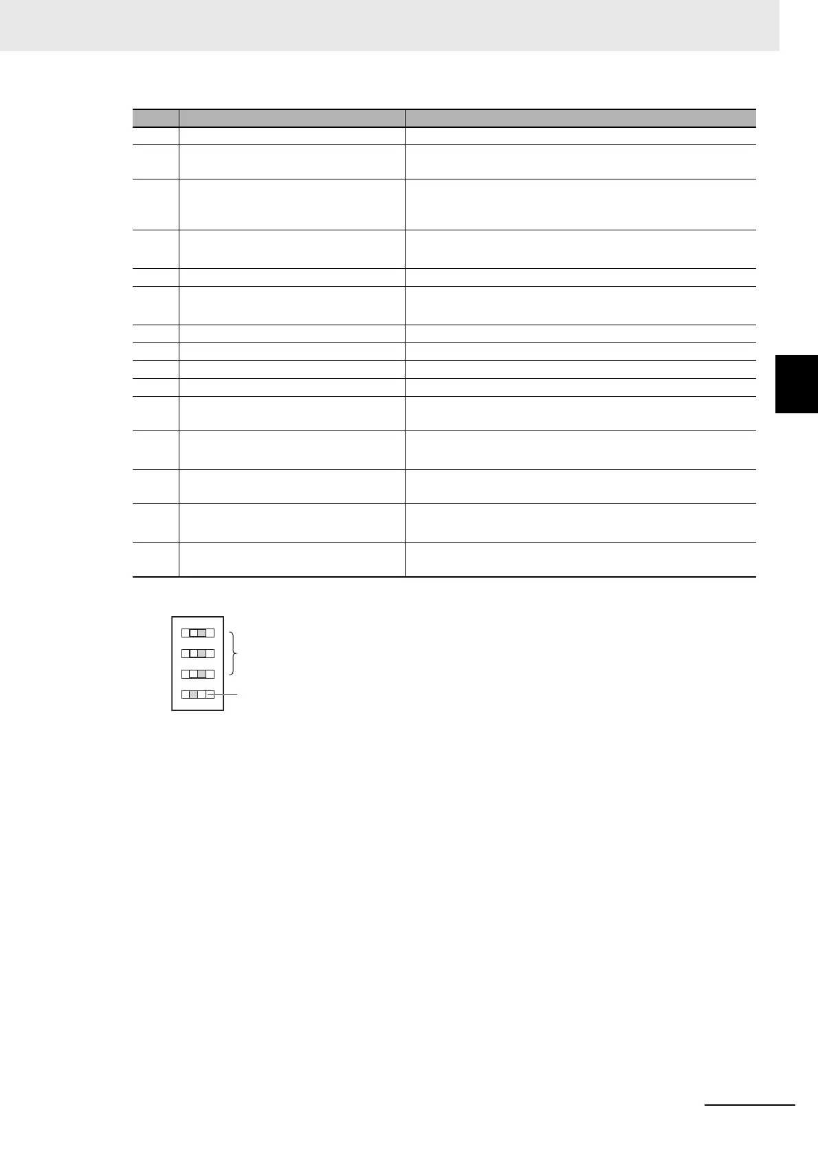
*1. To use Safe Mode, set the DIP switch as shown below and then turn ON the power supply to the Controller.
If the power supply to the Controller is turned ON with the CPU Unit in Safe Mode, the CPU Unit will start in
PROGRAM mode. Use the Safe Mode if you do not want to execute the user program when the power supply
is turned ON or if it is difficult to connect the Sysmac Studio.
For information on Safe Mode, refer to the NJ/NX-series Troubleshooting Manual (Cat. No. W503).
*2. Refer to the NJ/NX-series CPU Unit Software User’s Manual (Cat. No. W501) for details on backing up data.
Letter Name Function
 Loading...


