3 Configuration Units
3 - 8
NX-series NX1P2 CPU Unit Hardware User’s Manual (W578)
• Do not turn OFF the power supply to the Controller while the BUSY indicator flashes. While
the BUSY indicator is lit, the user program and settings in the CPU Unit are being backed up
in the built-in non-volatile memory. The data will not be backed up if the power supply is
turned OFF. The next time that the Controller is started, a Controller error in the major fault
level will occur and operation will stop.
• Do not turn OFF the power supply or remove the SD Memory Card while SD Memory Card
access is in progress (i.e., while the SD BUSY indicator flashes). Data may become cor-
rupted, and the Controller will not operate correctly if it uses corrupted data. To remove an
SD Memory Card from the CPU Unit when power is supplied to the CPU Unit, press the SD
Memory Card power supply switch and wait for the SD BUSY indicator and SD PWR indica-
tor to turn OFF before you remove the SD Memory Card.
You can check the operation status of the CPU Unit with the CPU Unit status indicators (POWER,
RUN, and ERROR indicators).
Refer to 6-1 Operation after an Error on page 6-2 for the procedures to check the operation status of
the CPU Unit.
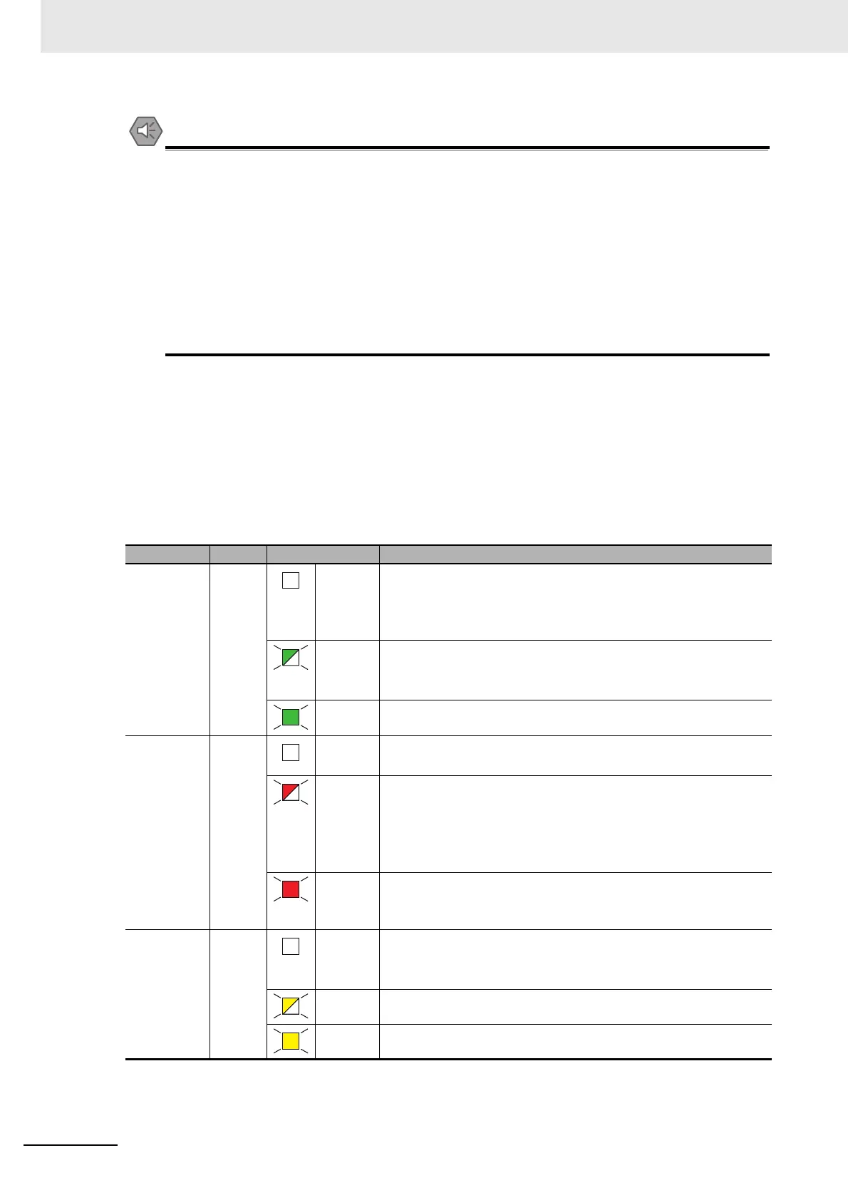
Built-in EtherNet/IP (Port 1) Status Indicators
These indicators show the operation status of the built-in EtherNet/IP port of the CPU Unit.
Indicator Color Status Meaning
NET RUN Green Not lit. You cannot perform Ethernet communications.
• The power supply is OFF or the CPU Unit was reset.
• A MAC address error or communications Controller error
occurred.
Flashing Ethernet communications are in progress.
• Tag data link connection establishment in progress.
• IP address acquisition with BOOTP in progress.
Lit. Normal startup status.
NET ERR Red Not lit. There are no Ethernet communications errors.
• The power supply is OFF or the CPU Unit was reset.
Flashing An error for which the user can recover operation occurred.
• An error occurred in TCP/IP communications or CIP communica-
tions.
• FTP server setting error, NTP server setting error, etc.
• Tag data link setting error, tag data link verification error, etc.
Lit. An error for which the user cannot recover operation occurred.
• A MAC address error or communications Controller error
occurred.
LINK/ACT Yellow Not lit. A link was not established.
• The cable is not connected.
• The power supply is OFF or the CPU Unit was reset.
Flashing The link is established, and data communications are in progress.
Lit. The link was established.
 Loading...


