EasyManuals Logo

Omron NX1P2 series User Manual

Omron NX1P2 series
340 pages
To Next Page IconTo Next Page
To Previous Page IconTo Previous Page
Page #95 background imageLoading...
Page #95 background image
3 - 23
3 Configuration Units
NX-series NX1P2 CPU Unit Hardware Users Manual (W578)
3-3 Serial Communications Option Board
3
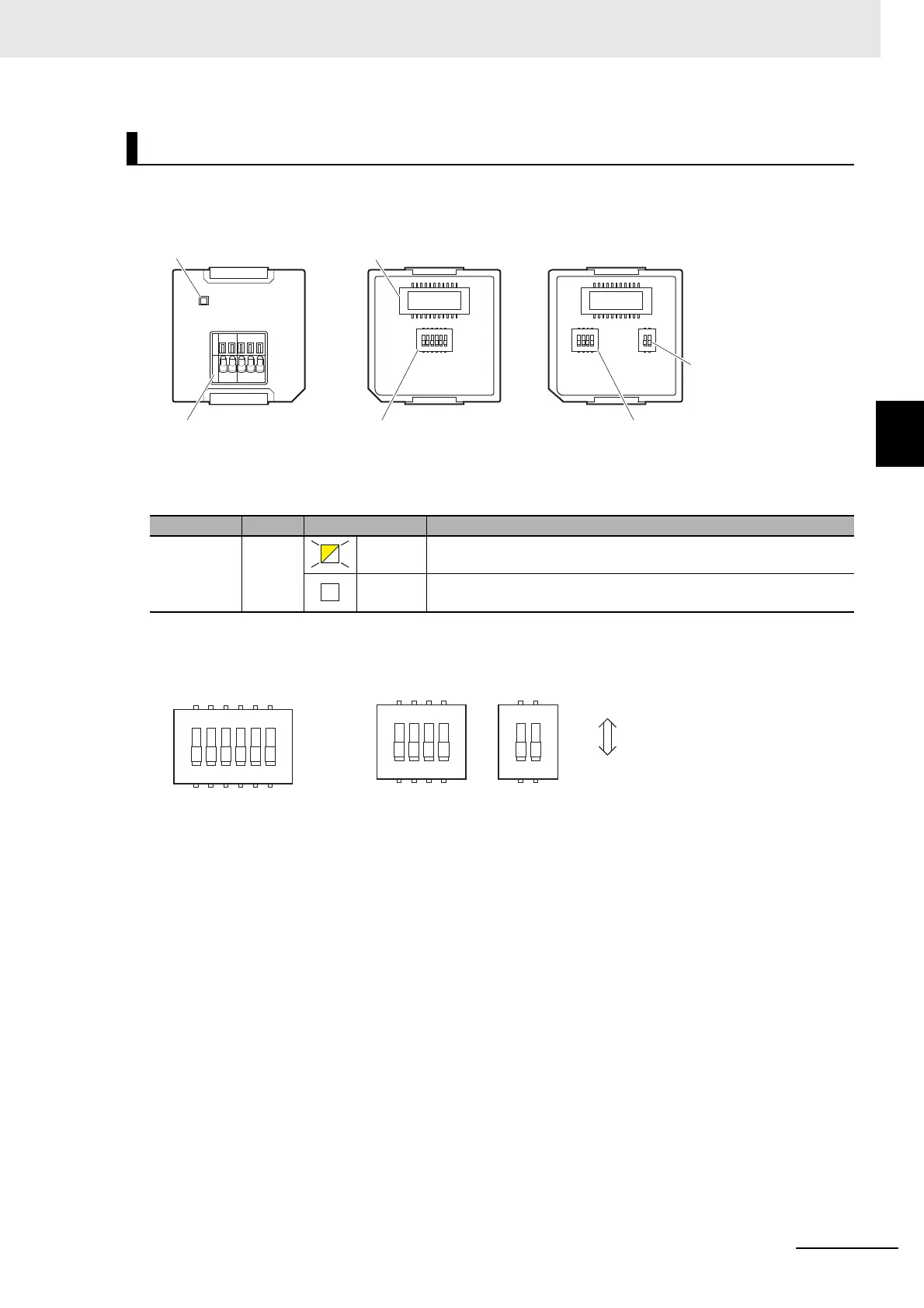
3-3-3 Part Names and Functions
Communications Status Indicator
Operation Setting DIP Switch
RS-422A/485 Option Board (NX1W-CIF11/NX1W-CIF12)
Indicator Color Status Description
COMM Yellow Lit. Communications are being performed.
Not lit. Communications are not performed.
RS-422A/485 terminal
block
Operation setting DIP
switch (SW1)
Operation setting DIP
switch (SW1)
Operation setting DIP
switch (SW2)
Communications
status indicator
CPU Unit connector
Front Back (CIF11) Back (CIF12)
SW 1
1
2
3
4
5
6
O
N
1
2
3
4
O
N
1
2
O
N
SW 1 SW 2
COMM
RDA- RDB+ SDA- SDB+ SHLD
CIF11
CIF12
1
2
3
4
5
6
O
N
1
2
3
4
O
N
1
2
O
N
SW1SW1 SW2
OFF ON

Table of Contents

Other manuals for Omron NX1P2 series

Questions and Answers:

Question and Answer IconNeed help?

Do you have a question about the Omron NX1P2 series and is the answer not in the manual?

Omron NX1P2 series Specifications

General IconGeneral
ModelNX1P2 Series
ManufacturerOmron
TypeController
CPU Units1
Program Capacity5 MB
Data Memory Capacity128 KB
Ethernet Ports1
Serial Ports1
Built-in EtherNet/IP PortYes
Built-in EtherCAT PortYes
Built-in USB PortYes
SD Memory Card SlotYes
USB Port1
Power Supply Voltage24 VDC
Programming LanguageLadder, Structured Text, Function Block Diagram
Communication ProtocolsEtherNet/IP, EtherCAT, Serial (RS-232C)

Related product manuals