6-50
6-7 Object Dictionary
OMNUC G5-series AC Servomotors and Servo Drives User’s Manual (with Built-in EtherCAT Communications)
6
Drive Profile
The bits in the physical outputs of this object set the outputs of function signals allocated by servo
parameters 3400 to 3407, 3410, and 3411 hex.
The bit mask sets masks for the physical outputs.
Bit Descriptions for Sub-index 1
The gain can be switched when realtime autotuning is disabled and gain 2 is enabled.
Speed loop P/PI control can be switched when realtime autotuning and gain 2 are disabled.
Set all reserved bits to 0.
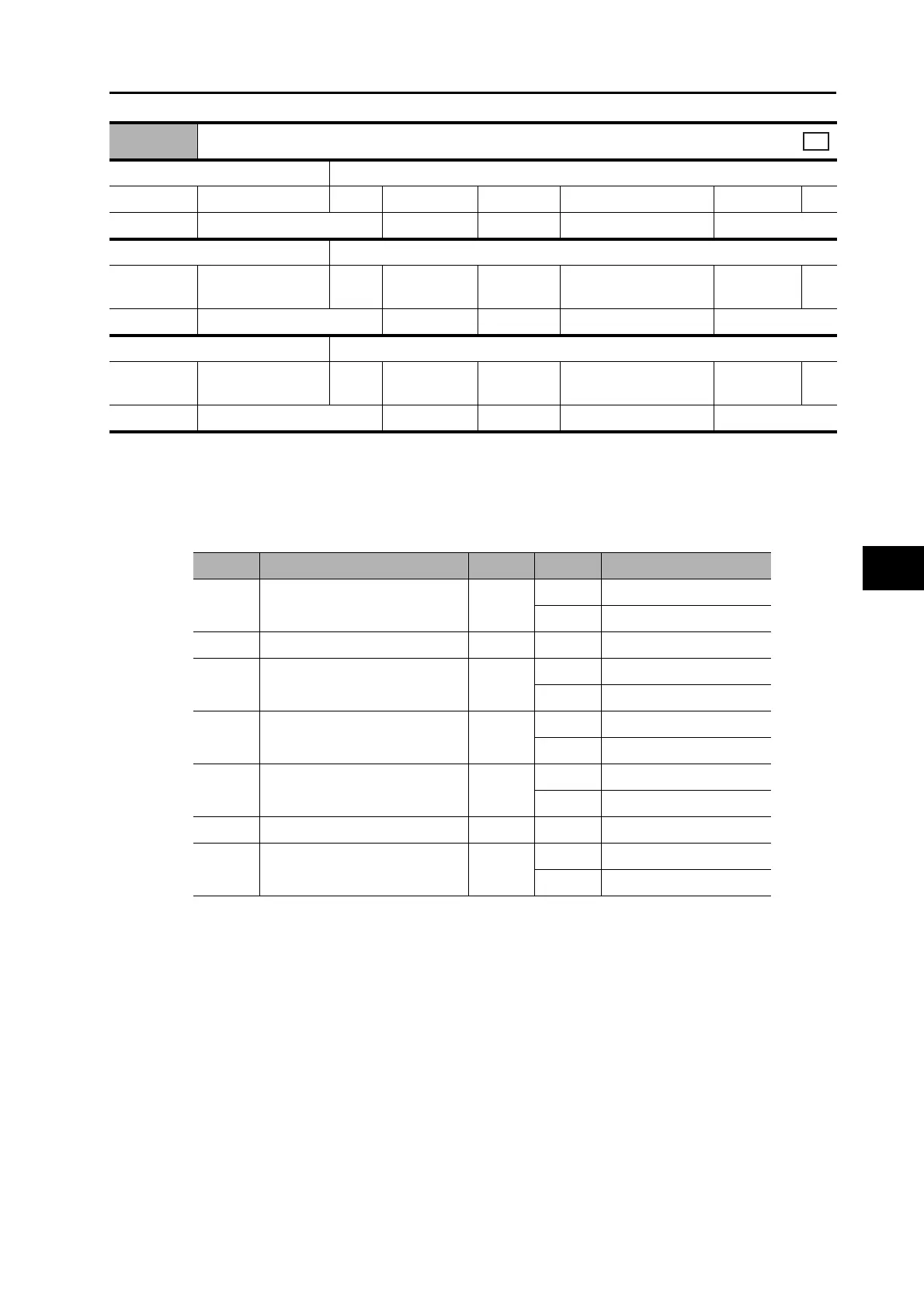
60FE hex
Digital outputs
Sub-index 0 Number of entries
Range − Unit − Default 02 hex Attribute −
Size 1 byte (U8) Access RO PDO map Not possible
Sub-index 1 Physical outputs
Range
0000 0000 to FFFF
FFFF hex
Unit − Default 0000 0000 hex Attribute A
Size 4 bytes (U32) Access RW PDO map Possible
Sub-index 2 Bit mask
Range
0000 0000 to FFFF
FFFF hex
Unit − Default 0000 0000 hex Attribute B
Size 4 bytes (U32) Access RW PDO map Not possible
All
Bit Signal name Symbol Code Description
0
Set brake (Brake Interlock
Output)
BKIR
0 don’t set brake
1 set brake
1 to 15 Reserved − 0 −
16
Remote Output 1
R-OUT1
0OFF
1ON
17
Remote Output 2
R-OUT2
0OFF
1ON
24
Gain Switching
G-SEL
0Gain 1
1Gain 2
25 Reserved − 0 −
26
Speed Loop P/PI Control
P/PI
0 PI control
1 P control
 Loading...


