6-51
6-7 Object Dictionary
OMNUC G5-series AC Servomotors and Servo Drives User’s Manual (with Built-in EtherCAT Communications)
6
Drive Profile
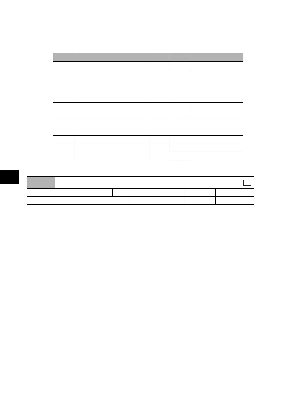
Bit Descriptions for Sub-index 2
This object indicates the type of motor that is connected.
It is always 3 (PM synchronous motor) for OMNUC G5-series Servo Drives.
Bit Signal name Symbol Code Description
0
Set brake Mask (Brake Interlock
Output Mask)
BKIR
0 Set brake disable output
1 Set brake enable output
1 to 15 Reserved −− −
16
Remote Output 1 Mask
R-OUT1
0 R-OUT1 disable output
1 R-OUT1 enable output
17
Remote Output 2 Mask
R-OUT2
0 R-OUT2 disable output
1 R-OUT2 enable output
24
Gain Switching Mask
G-SEL
0 Switch setting disable
1 Switch setting enable
25 Reserved −− −
26
Speed Loop P/PI Control Mask
P/PI
0 Switch setting disable
1 Switch setting enable
6402 hex
Motor type
Range − Unit − Default 3 Attribute −
Size 2 bytes (U16) Access RO PDO map Not possible
All

 Loading...


