2-35
2-4 External and Mounting Dimensions
OMNUC G5-series AC Servomotors and Servo Drives User’s Manual (with Built-in EtherCAT Communications)
2
Models and External Dimensions
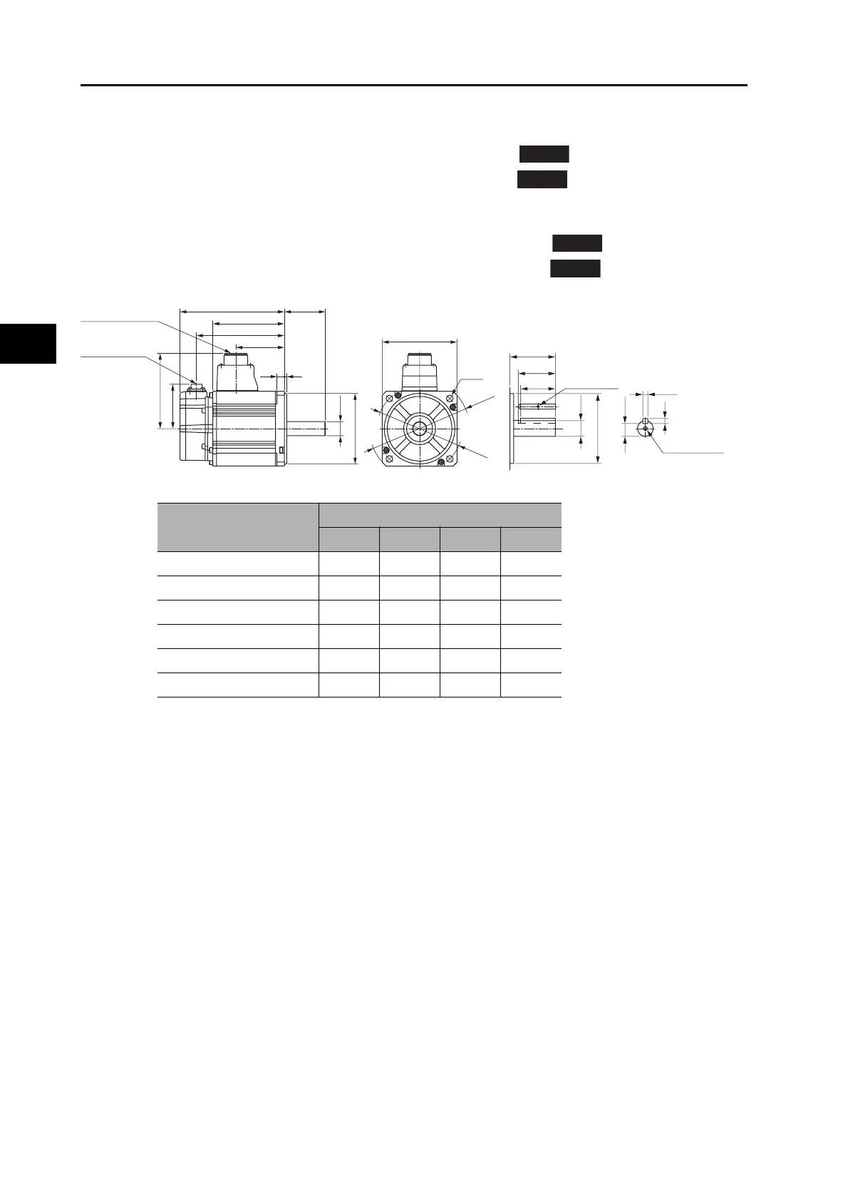
1 kW/1.5 kW/2 kW (without Brake)
R88M-K1K030H (-S2)/-K1K530H (-S2)/-K2K030H (-S2)
R88M-K1K030T (-S2)/-K1K530T (-S2)/-K2K030T (-S2)
1 kW/1.5 kW/2 kW (with Brake)
R88M-K1K030H-B (S2)/-K1K530H-B (S2)/-K2K030H-B (-S2)
R88M-K1K030T-B (S2)/-K1K530T-B (S2)/-K2K030T-B (-S2)
Note: The standard models have a straight shaft. Models with a key and tap are indicated with S2 at the
end of the model number.
Model
Dimensions (mm)
LL LM KB1 KB2
R88M-K1K030@ 141 97 66 119
R88M-K1K530@ 159.5 115.5 84.5 137.5
R88M-K2K030@ 178.5 134.5 103.5 156.5
R88M-K1K030@-B@ 168 124 66 146
R88M-K1K530@-B@ 186.5 142.5 84.5 164.5
R88M-K2K030@-B@ 205.5 161.5 103.5 183.5
INC
ABS
INC
ABS
φ115
4-φ9
42
45
55
φ135
100×100
Encoder
connector
Motor and brake
connector
M3, through
6h9
φ
19h6
6
15.5
φ95h7
M5 (depth 12)
(Shaft end specifications with key and tap)
LM
KB2
KB1
55LL
3
101
60
10
φ
19h6
φ95h7
 Loading...


