3-10
3-1 Servo Drive Specifications
OMNUC G5-series AC Servomotors and Servo Drives User’s Manual (with Built-in EtherCAT Communications)
3
Specifications
R88D-KN06F-ECT-R/-KN10F-ECT-R/-KN15F-ECT-R/-KN20F-ECT-R
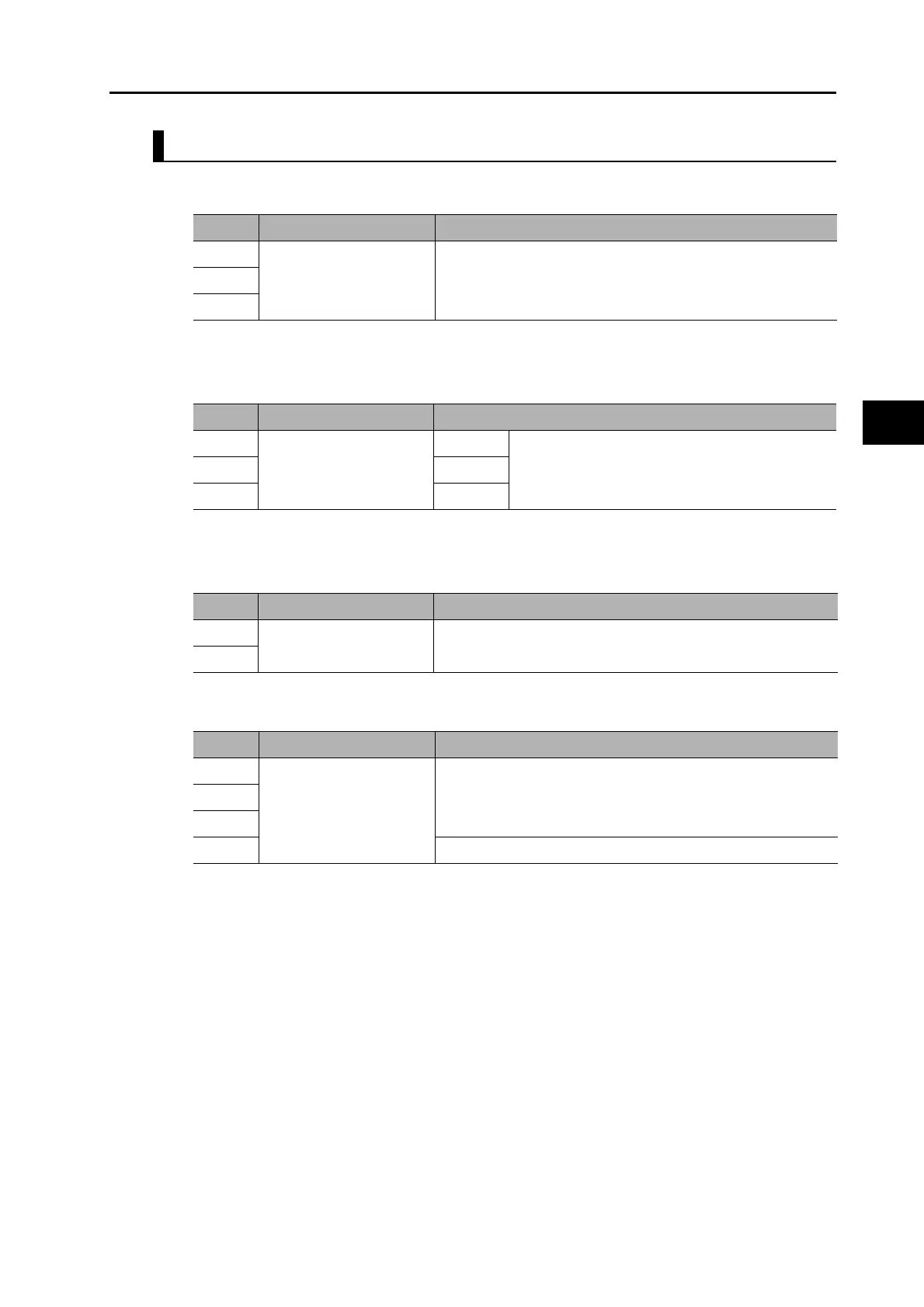
Main Circuit Connector Specifications (CNA)
Motor Connector Specifications (CNB)
Control Circuit Connector Specifications (CNC)
External Regeneration Resistor Connector Specifications (CND)
Symbol Name Function
L1 Main circuit power supply
input
R88D-KN@F-ECT-R
600 W to 1.5 kW: 3-phase: 380 to 480 VAC (323 to 528 V)
50/60 Hz
L2
L3
Symbol Name Function
U Motor connection
terminals
Phase U These are the output terminals to the Servomotor.
Be sure to wire them correctly.
V Phase V
WPhase W
Symbol Name Function
24 V Control circuit power
supply input
24 VDC ± 15%
0 V
Symbol Name Function
B1 External Regeneration
Resistor connection
terminals
Normally B2 and B3 are connected.
If there is high regenerative energy, remove the short-circuit bar
between B2 and B3 and connect an External Regeneration
Resistor between B1 and B2.
B2
B3
NC Do not connect.

 Loading...


