4 System Design
4-22
G5 Series AC Servo Drives With Built-in EtherCAT Communications, Linear Motor Type
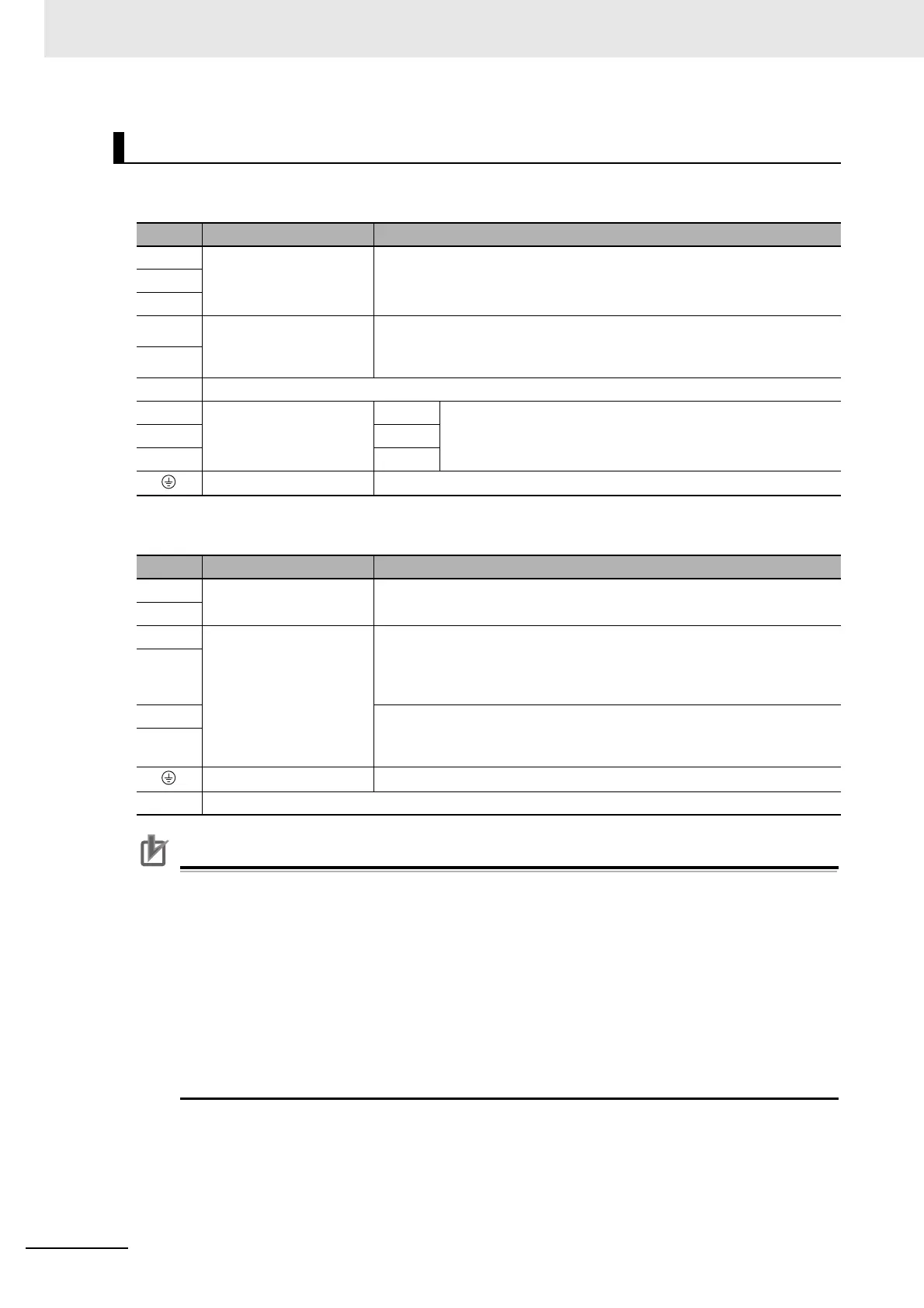
Terminal Block Specifications, Left Terminal Block (TB1)
Terminal Block Specifications, Right Terminal Block (TB2)
Precautions for Correct UsePrecautions for Correct Use
• Tighten the frame ground screw to a torque of 1.4 to 1.6 N·m (M5).
• Tighten the left terminal block screws to a torque of 2.0 to 2.4 N·m (M5). Exceeding the
maximum allowable torque for terminal block screws may cause damage to the terminal block.
• Tighten the fixing screw of the left terminal block cover to a torque of 0.3 to 0.5 N·m (M3).
• Tighten the right terminal block screws to a torque of 1.0 to 1.7 N·m (M5). Exceeding the
maximum allowable torque for terminal block screws may cause damage to the terminal block.
• Tighten the fixing screw of the right terminal block cover to a torque of 0.19 to 0.21 N·m (M3).
• If you are connecting an External Regeneration Resistor, set the Regeneration Resistor
Selection servo parameter object (3016 hex).
• Do not connect any External Regeneration Resistors between B1 and NC.
R88D-KN75F-ECT-L
Symbol Name Function
L1 Main circuit power supply
input
3-phase 380 to 480 VAC (323 to 528 VAC) 50/60 Hz
L2
L3
B1 External Regeneration
Resistor connection
terminals
Connect an External Regeneration Resistor between B1 and B2.
B2
NC Do not connect.
U Motor connection
terminals
Phase U These are the output terminals to the Linear Motor.
Be sure to wire them correctly.
V Phase V
W
Phase W
Frame ground This is the ground terminal. Ground to 100 or less.
Symbol Name Function
24 V Control circuit power
supply input
24 VDC (20.4 to 27.6 VDC)
0 V
DB1 Dynamic Brake Resistor
control terminals
These terminals are used to control the MC for externally connected
dynamic brake resistance. The output contact specifications are 1 A max.
at 300 VAC/100 VDC max.
Connect them if required.
DB2
DB3 Normally DB3 and DB4 are shorted.
When using an externally connected Dynamic Brake Resistor, remove the
short bar from between DB3 and DB4.
DB4
Frame ground This is the ground terminal. Ground to 100 or less.
NC Do not connect.

 Loading...

