7 Applied Functions
7-4
G5 Series AC Servo Drives With Built-in EtherCAT Communications, Linear Motor Type
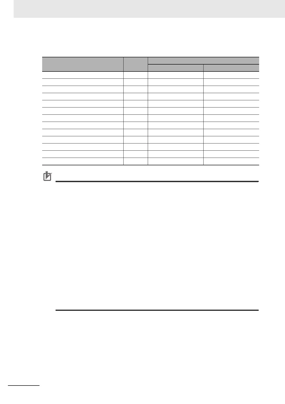
Function Number Table
The set values to be used for allocations are as follows:
Precautions for Correct UsePrecautions for Correct Use
• Do not use any settings other than the settings listed.
• Do not allocate the same function to more than one input signal. If you allocate the same
function to more than one input signal, and Interface Input Duplicate Allocation Error 1 (Error
No. 33.0) or Interface Input Duplicate Allocation Error 2 (Error No. 33.1) will occur.
• The External Latch Inputs 1, 2, and 3 (EXT1, EXT2 and EXT3) can be allocated only to IN5 to
IN7. If you allocate them to any other inputs, an External Latch Input Allocation Error (Error
No. 33.8) will occur.
• If you use the External Latch Input 1, 2, or 3 (EXT1, EXT2 or EXT3), you must set it for all
control modes. Otherwise, an External Latch Input Allocation Error (Error No. 33.8) will occur.
• The External Latch Inputs 1, 2, and 3 (EXT1, EXT2 and EXT3) can be set only to NO
(normally open) contacts. If set to NC (normally close) contacts, an External Latch Input
Allocation Error (Error No. 33.8) will occur.
• The control input pins that are disabled do not affect the operation. It also does not affect the
response in EtherCAT Communications.
• The functions that are used by more than one control mode must be allocated to the same pin,
in the same logic. If they are allocated to different pins, an Interface Input Duplicate Allocation
Error 1 (Error No. 33.0) or an Interface Input Duplicate Allocation Error 2 (Error No. 33.1) will
occur.
If the logic is inconsistent, an Interface Input Function Number Error 1 (Error No. 33.2) or an
Interface Input Function Number Error 2 (Error No. 33.3) will occur.
Signal name Symbol
Set value
NO NC
Disabled 00 hex Setting not available
Positive Drive Prohibition Input POT 01 hex 81 hex
Negative Drive Prohibition Input NOT 02 hex 82 hex
Immediate Stop Input STOP 14 hex 94 hex
External Latch Input 1 EXT1 20 hex Setting not available
External Latch Input 2 EXT2 21 hex Setting not available
Origin Proximity Input DEC 22 hex A2 hex
External Latch Input 3 EXT3 2B hex Setting not available
Positive Force Limit Input PCL 2C hex AC hex
Negative Force Limit Input NCL 2D hex AD hex
Monitor Input 0 MON0 2E hex AE hex
Monitor Input 1 MON1 2F hex AF hex
Monitor Input 2 MON2 30 hex B0 hex

 Loading...

