6-9
6-3 Using the Parameter Unit
6
Operation
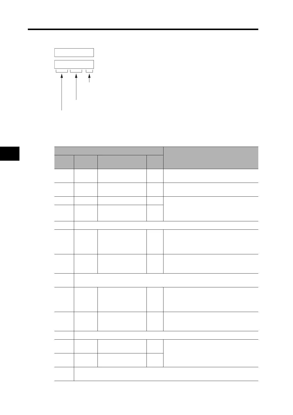
I/O Signal Status
Displays the status of the control input and output signals connected to CN1.
Input Signals
iknk0k0. ka
oktk0k9. k-k
in
ot
a
: ON
-
: OFF or disabled
Input signal No. 00 ON
Output signal No. 09 OFF or disabled
Signal No. display (0 to 1F hex)
: Input
: Output
CN1
Function
Signal
No.
Symbol Name
Pin
No.
00 RUN RUN Command 2
If the RUN signal turns ON, a Servo lock oc-
curs, and is displayed.
01 RESET Alarm Reset 3
If the RESET signal turns ON, the alarm is re-
set, and is displayed.
02 NOT Reverse Drive Prohibit 7 Regardless of the setting of the Drive Prohibit
Input Selection (Pn04), “
-” is displayed when
the POT/NOT signal turns ON, and is
displayed when it turns OFF.
03 POT Forward Drive Prohibit 8
04 Not used.
05 VZERO
Zero Speed
Designation
5
The Servomotor stops and is displayed if
this signal turns OFF when the Zero Speed
Designation/Torque Limit Switch (Pn06) is set
to 1.
06 GESEL
Electronic Gear
Switch
6
If the GESEL signal turns ON, the Electronic
Gear Ratio Numerator 2 is enabled, and is
displayed.
07 to
08
Not used.
09 GSEL Gain Switch 5
When the Gain Switching Input Operating
Mode Selection (Pn30) is set to 0 and the
GSEL signal turns OFF, PI operation is en-
abled and “
-” is displayed.
0A ECRST
Deviation Counter
Reset
4
Used to reset the deviation counter.
When the ECRST signal turns ON, is
displayed.
0B Not used.
0C VSEL1
Internally Set Speed
Selection 1
6
When VSEL1 and VSEL2 are ON, is
displayed.
0D VSEL2
Internally Set Speed
Selection 2
4
0E to
1F
Not used.
a
a
 Loading...


