6-10
6-3 Using the Parameter Unit
6
Operation
Output Signals
Switching between Input Signals and Output Signals
The following procedure can also be used to switch between input and output.
CN1
Function
Signal
No.
Symbol Name
Pin
No.
00 Not used.
01 /ALM Alarm 9
If an alarm occurs, the /ALM signal turns
OFF, and is displayed.
02 INP
Positioning
Completed
10
When a workpiece is positioned within the set-
ting range, the Positioning Completion Range
(Pn60), INP turns ON and is displayed.
03 BKIR Brake Interlock 11
The output transistor for the electromagnetic
brake signal turns ON, and is displayed.
04 --- Zero Speed Detection 12
When the Warning Output Selection (Pn09) is
set to 1, and Zero Speed Detection output
turns ON, is displayed.
05 --- Torque Limiting 12
When the Warning Output Selection (Pn09) is
set to 0, and Torque Limiting output turns ON,
is displayed.
06 to
08
Not used.
09 TGON
Servomotor Rotation
Speed Detection
10
When the actual motor speed exceeds the Ro-
tation Speed for Servomotor Rotation Detec-
tion (Pn62), TGON turns ON and is
displayed.
0A to
1F
Not used.
aa
a
iknk0k0. ka
ikn.0k0k kak
okt.0k0k k-k
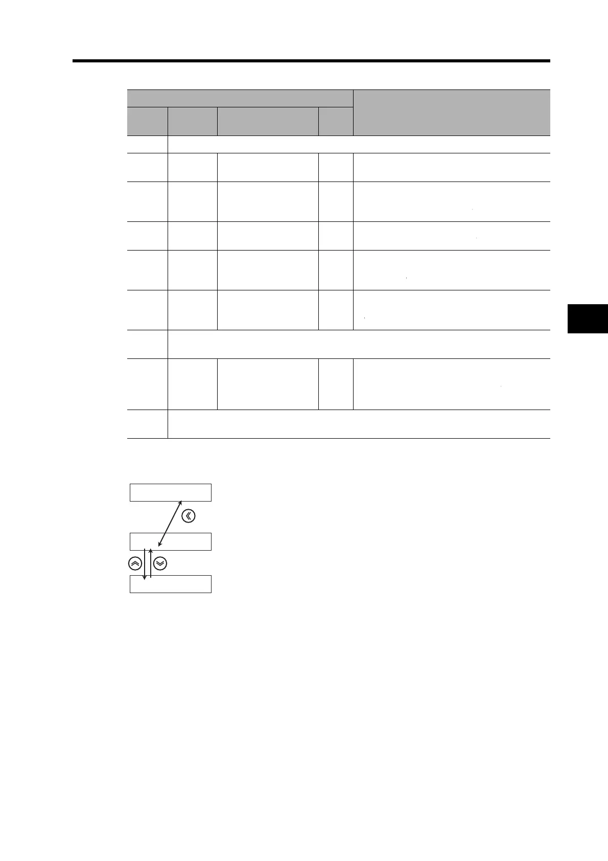
If the decimal point is at the right of the signal number,
the signal number can be changed.
Move the flashing decimal point with the Shift key.
If the decimal point is at the right of the input/output
indication, you can switch between inputs and outputs.
Switch between inputs and outputs with the Increment/Decrement keys.
 Loading...


