4-94
4-2 Function Mode
4
Functions
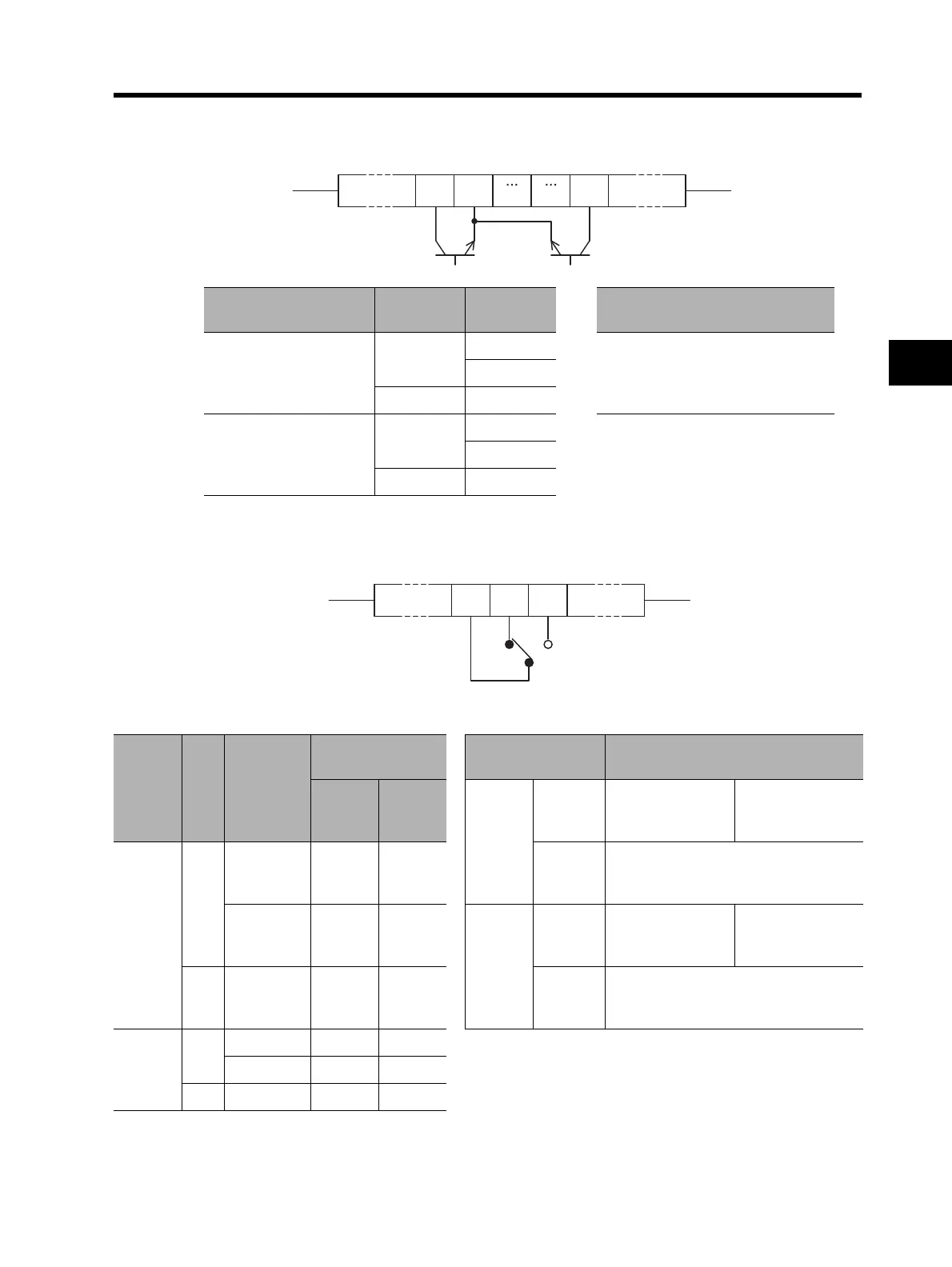
Specifications of Multi-function Output Terminals P1 to P5
•Below are the specifications of multi-function output terminals P1 to P5.
Specifications of the Relay Output Terminals
•The relay output terminals have an SPDT contact configuration. Below is its operation.
(Example) When the relay output terminals are used for alarm
C031 to C035 set values
Power
supply
Output
status
Electrical characteristics
00
(NO contact)
ON
ON
Between each terminal and PC
Voltage drop 4 V max. at power-on
Max. allowable voltage: 27 V DC
Max. allowable current: 50 mA
OFF
OFF
01
(NC contact)
ON
ON
OFF
OFF
Inside the Inverter
P5 PC P1
Inside the Inverter
MC MA MB
(Default value: C036 = 01)
C036
set
values
Power
Inverter
status
Output terminal
status
Resistance load Inductive load
MA-MC MB-MC
MA-MC
Max.
contact
capacity
250 V AC, 2 A
30 V DC, 8 A
250 V AC, 0.2 A
30 V DC, 0.6 A
00
ON
Abnormal Closed Open
Min.
contact
capacity
100 V AC, 10 mA
5 V DC, 100 mA
Normal Open Closed
MB-MC
Max.
contact
capacity
250 V AC, 1 A
30 V DC, 1 A
250 V AC, 0.2 A
30 V DC, 0.2 A
OFF Open Closed
Min.
contact
capacity
100 V AC, 10 mA
5 V DC, 100 mA
01
(Default)
ON
Abnormal Open Closed
Normal Closed Open
OFF Open Closed
 Loading...


